
Description
Key Technical Specifications
-
Model Number: 9905-002
-
Manufacturer: Woodward Inc.
-
Product Family: SPM-A Synchronizer Series
-
Power Supply: 115 VAC RMS or 230 VAC RMS (dual voltage, selectable), 50/60 Hz
-
Power Consumption: 10 W maximum
-
Phase Angle Matching: ±10° (adjustable)
-
Voltage Matching Capability: Within 1% to 5% of bus voltage
-
Frequency Matching: Biases offline generator speed to match bus frequency
-
Output Options:
-
High impedance output (for 2301 load sharing systems)
-
Low impedance output (for 2301A, EPG, and 2500 load sharing)
-
EPG output (for EPG controls without load sharing)
-
-
Breaker Close Contact: Relay output initiates circuit breaker closure when sync criteria met
-
Operating Modes: RUN, CHECK, PERMISSIVE, OFF (front panel selectable)
-
Synchronization Method: Analog bias signals to governor speed control
-
Operating Temperature: -20°C to +70°C (-4°F to +158°F)
-
Storage Temperature: -40°C to +85°C (-40°F to +185°F)
-
Relative Humidity: 5% to 95% non-condensing
-
Mounting: Panel-mounted in control cabinet
-
Dimensions: Approximately 200 mm × 120 mm × 50 mm
-
Weight: 0.6 kg (1.3 lb)
-
National Stock Number: 6625-01-456-7168
-
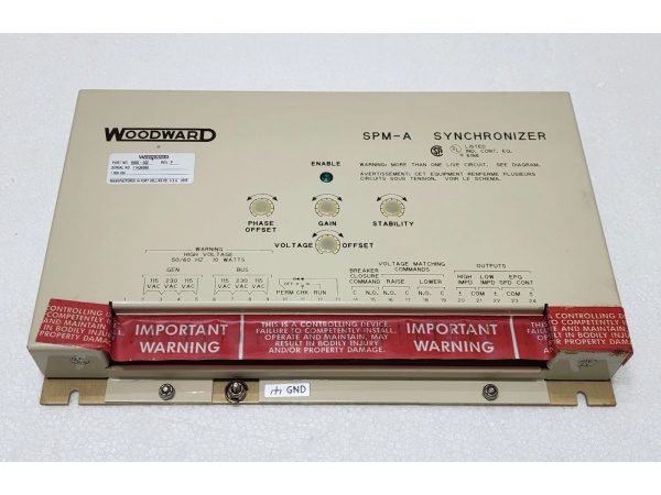
Front Panel Indicators: Sync meter (synchroscope), voltage difference meter, mode selector switch

Woodward 9905-002
Field Application & Problem Solved
In the field, the biggest challenge with manual paralleling is the human factor—operators trying to match speed and phase by watching lights or meters, then closing the breaker at the wrong instant. A 10-degree phase difference at 480V can produce inrush currents of 8-10 times rated, snapping shafts, stripping gears, or welding breaker contacts. The 9905-002 eliminates this risk by automatically biasing the offline generator’s speed to achieve precise phase alignment and initiating breaker closure at the exact moment of synchronism.
You will typically find this module in power plants running multiple diesel or gas generator sets in island mode—think mining operations, remote construction camps, marine switchboards, or industrial facilities with critical backup power. It’s designed to work with Woodward’s 2301A load sharing controls, EPG governors, or older 2301/2500 analog systems. The 9905-002 is the “brain” that watches the bus and the incoming generator, calculates the slip frequency, and gently nudges the governor until the vectors align.
Its core value is preventing the catastrophic damage that comes from out-of-phase paralleling while eliminating the need for skilled operators to perform manual synchronization. The module continuously monitors voltage magnitude, phase angle, and frequency difference between the bus and the incoming machine. When all parameters fall within set limits, it closes the breaker contact. The selectable impedance outputs are critical—if you’re interfacing with a 2301A system, you need the low-impedance output; for older 2301 systems, high impedance. Get this wrong and the bias signal won’t drive the governor properly, resulting in hunting or failed synchronization.
Installation & Maintenance Pitfalls (Expert Tips)
Output Impedance Selection is Critical
The most common field mistake is wiring the wrong output impedance for your governor system. The 9905-002 has three distinct output configurations: high impedance for legacy 2301 load sharing, low impedance for 2301A/EPG/2500 systems, and EPG output for non-load-sharing applications. I’ve seen technicians wire the high-impedance output to a 2301A control and wonder why the generator never syncs—the bias signal is too weak to overcome the 2301A’s input impedance. Check your governor manual and verify which input terminal expects what signal level. The jumper or switch selection for output type is usually on the rear terminal block—confirm it with a multimeter before power-up.
Voltage Transformer Phasing Will Ruin Your Day
The 9905-002 compares bus voltage against generator voltage. If your PTs are not phased identically—same polarity, same phase rotation—the module will see 120 degrees of separation when the machines are actually in phase, or vice versa. This causes the synchroscope to spin backwards or freeze at an apparent “sync” point that’s actually 180 degrees out. Always verify PT phasing with a phase angle meter during commissioning. Mark the PT secondary leads clearly; I’ve seen installations where maintenance crews swapped bus and generator PT leads during routine work, resulting in immediate breaker trip or equipment damage on the next start attempt.
The “Check” Mode is Your Friend—Use It
Rookies often flip the mode switch straight to “RUN” and hope for the best. The “CHECK” mode allows you to verify the synchronizer’s operation without actually closing the breaker. In CHECK mode, the module performs all measurements and bias functions but blocks the breaker close contact. You can watch the synchroscope needle settle at the 12-o’clock position and confirm the voltage difference meter reads near zero. If the needle hunts or won’t stabilize, you’ve got a governor response problem or incorrect speed sensing. Never commission a new installation without running in CHECK mode for several slip cycles first.
Grounding and Shielding are Non-Negotiable
The analog bias outputs from the 9905-002 are susceptible to EMI from power cables, VFDs, and radio equipment. Use shielded twisted pair for all bias signal wiring, grounding the shield at the synchronizer end only. I’ve diagnosed installations where unshielded wiring running parallel to 480V feeder cables induced enough noise to cause erratic governor behavior—engines surging 50 RPM for no apparent reason. The shield drain wire should terminate at terminal 22 or the designated ground lug on the chassis, never at both ends.
Don’t Ignore the Voltage Difference Setting
The factory default for voltage matching is typically ±5%, but this is often too loose for sensitive loads. If your generator voltage is 5% high when the breaker closes, you’ll see a reactive power surge as the generator immediately tries to correct the bus voltage. For precision applications, adjust the voltage window to ±1% or ±2%. This requires patience during commissioning—you’ll need to tweak the generator AVR setpoint carefully—but it prevents the “thump” and current surge that comes from paralleling mismatched voltages.
Woodward 9905-002
Technical Deep Dive & Overview
The Woodward 9905-002 is an analog automatic synchronizer from the SPM-A series, representing mature technology that predates microprocessor-based digital synchronizers like the DSLC or EasyGen series. It operates as a closed-loop control system that compares the voltage vector of an offline generator against the live bus or utility, then generates corrective bias signals to drive the generator into synchronism.
The module receives voltage inputs from both the bus and generator potential transformers (PTs), typically 120V or 240V secondary depending on system voltage. Internal circuitry derives phase angle, frequency difference, and voltage magnitude difference. The phase angle is displayed on a front-panel synchroscope meter—a rotating LED or needle display that shows the relative position of the generator vector to the bus vector. When the generator is running faster than the bus, the needle rotates clockwise; slower, counter-clockwise.
The frequency difference circuit generates a DC bias signal proportional to the slip frequency. This bias is applied to the governor speed control input—on a 2301A system, this connects to the speed bias terminals. The bias polarity is arranged to slow a fast generator or speed up a slow one, effectively pulling the generator into phase lock with the bus. As the frequency difference approaches zero, the phase angle rotation slows, allowing the breaker close circuit to energize when the vectors align within the set window (typically ±10 electrical degrees).
The voltage matching circuit works similarly, comparing generator and bus PT signals and providing a raise/lower output to the automatic voltage regulator (AVR) if equipped, or simply blocking synchronization if voltage difference exceeds set limits. The breaker close output is a relay contact that remains open until all parameters—phase, frequency, and voltage—fall within acceptable windows simultaneously. This contact typically drives the breaker close coil through an appropriate interposing relay.
Unlike modern digital synchronizers that communicate via Modbus or CANbus, the 9905-002 is entirely hardwired and analog. There are no passwords, no software versions to track, no communication protocols to configure. This makes it extremely reliable in harsh environments but limits flexibility—adjustments require physical access to potentiometers inside the unit, and there’s no remote monitoring capability. The module is designed for continuous duty in generator control cabinets, with convection cooling and no moving parts except the front-panel meter mechanism.


