
Description
Hard-Numbers: Technical Specifications
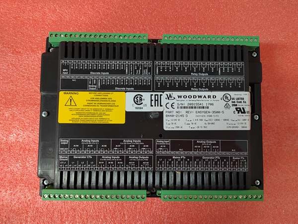
- Part Number: 8440-2189
- Power Supply: 90–250 VAC / 120–375 VDC (40-70 Hz)
- Voltage Sensing Inputs: 400 VAC (Line-to-Line True RMS)
- CT Input: …/5 A (True RMS)
- Analog Outputs: 2 Configurable (e.g., ±10V, ±20mA, 0-20mA, PWM)
- Discrete Outputs: 8 (Form C relay drivers)
- Discrete Inputs: 10 (12/24 VDC)
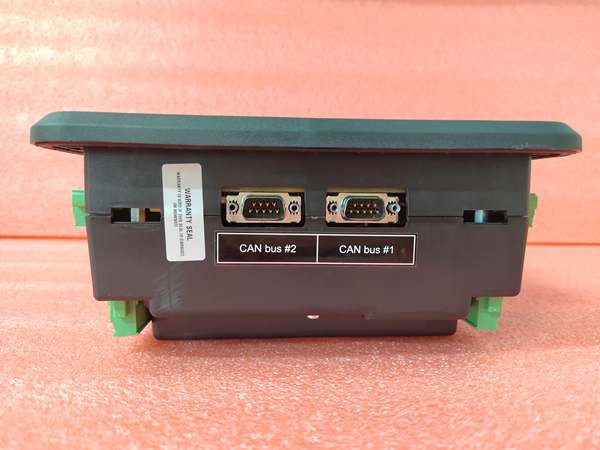
- Communications: USB, CANopen, RS-485
- Operating Temp: -20°C to +70°C
- Environmental Rating: IP66 (front face)
8440-2189
The Real-World Problem It Solves
Trying to manually parallel a 400V diesel genset with a live bus using analog meters is a recipe for mechanical disaster. A slight phase mismatch or frequency drift will trip breakers, damage prime movers, and wreck facility power quality. The 8440-2189 automates this high-risk maneuver by constantly monitoring generator and bus waveforms, then issuing precise throttle and voltage bias commands to achieve a bumpless connection.
Where you’ll typically find it:
- Retrofit jobs upgrading legacy SPM-D synchronizers in aging power plants.
- Main distribution panels of 400V standby diesel generators requiring automated utility paralleling.
- Microgrids utilizing multiple gas or diesel gensets to balance kW and kVAR loads.
It removes human error from the equation and protects the engine mechanically.
Hardware Architecture & Under-the-Hood Logic
This unit is a dedicated digital signal processor built to execute high-speed AC waveform math and closed-loop control algorithms. It sits between the PT/CT sensors and the engine governor/AVR, actively steering the prime mover rather than just monitoring it.
- Waveform Acquisition: The module samples the 400V Line-to-Line voltage and CT secondary current, calculating True RMS values to ignore harmonic distortion from modern VFDs.
- Phase Angle Tracking: It continuously computes the phase angle difference and slip frequency between the generator and the target bus.
- Bias Output Generation: Based on the deviation, it drives the governor (speed) and AVR (voltage) using configurable analog outputs or PWM pulses until the setpoints match.
- Breaker Actuation: Once the phase, frequency, and voltage are within the pre-programmed deadband, it triggers the discrete output to close the main breaker.
8440-2189
Field Service Pitfalls: What Rookies Get Wrong
Mismatched CT Polarity Causing Reverse Power Trips
New techs often wire the current transformers based solely on terminal labels without verifying the physical phase rotation. When the generator picks up load, the module reads negative kW, assumes the engine is motoring, and immediately trips the breaker to save the prime mover.
- Field Rule: Always perform a “bump test” by paralleling the generator momentarily at near-zero load. Watch the kW reading on the local display; if it goes negative when the load increases, swap the S1 and S2 leads on the CT secondary.
“Hunting” Caused by Improper Governor Tuning
A common mistake is maxing out the 8440-2189’s ramp rates, assuming faster is better for synchronization. This forces the governor into an aggressive chase, resulting in RPM oscillation (hunting) that can trip the machine on over/under frequency faults.
- Field Rule: Treat the synchronizer as a gentle guide, not a battering ram. Set the raise/lower ramp rates conservatively in the Toolkit software, and ensure the underlying governor PID loops are damped for stability before handing control over to the 8440-2189.
Forgetting to Configure the Voltage Divider Ratio
Installers sometimes assume selecting “400V” in the software is the only setting needed, overlooking the fact that the module needs the PT ratio to calculate actual bus voltage. The result is a synchronizer that refuses to issue a close command because it thinks the voltage is out of bounds.
- Field Rule: Double-check the “VT / PT Ratio” parameter in the USB Toolkit configuration. The 8440-2189 expects the primary and secondary voltage values to calculate its error margins accurately.
Commercial Availability & Pricing Note
Please note: The listed price is for reference only and is not binding. Final pricing and terms are subject to negotiation based on current market conditions and availability.


