
Description
Hard Numbers: Technical Specifications
(Note: Specific public datasheets for the 8440-1519 variant are limited. The following specs represent typical parameters for the Woodward 8440 EASyGen/SPM series. Please consult the official manual for exact figures.)
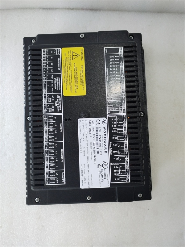
- Operating Voltage: 12/24 Vdc (9–32 Vdc range typical)
- Speed Sensor (MPU): 50–20,000 Hz input frequency typical
- Actuator Output: 0–200 mA (for proportional actuators)
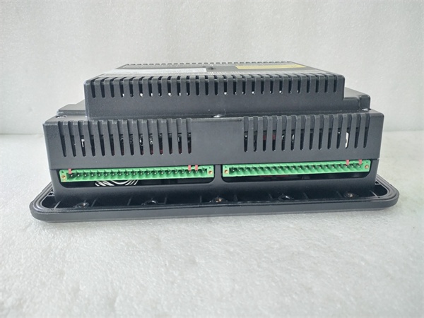
- Discrete Inputs: Multiple (typically 12–16 channels)
- Discrete Outputs: Multiple Relay Outputs (10A @ 250VAC / 30VDC typical)
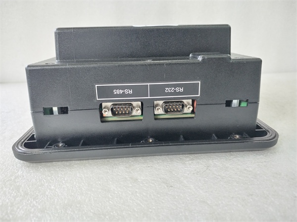
- Communication Interfaces: RS-232, RS-485, CANbus, Ethernet (Modbus RTU/ASCII/TCP)
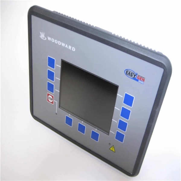
- Display: Backlit LCD (graphical/text based on specific sub-model)
- Operating Temperature: -20°C to +70°C (-4°F to 158°F) typical
- Protection Rating: NEMA 4 / IP65 (front panel) typical for panel mount variants
- Compliance: UL, CE, ABS, BV, DNV, GL (typical for marine/offshore variants)
The Real-World Problem It Solves
In modern power generation, especially in applications involving multiple generators (islands, data centers, marine vessels), simply turning a generator on and off isn’t enough. The system must seamlessly transition between standalone operation, parallel operation with other generators, and utility paralleling. Manual synchronization is dangerous and imprecise, risking damaging inrush currents, voltage collapses, or unstable frequencies that can trip breakers and crash entire power grids.
The Woodward 8440-1519 acts as the central nervous system for complex generator paralleling. It automates the entire process of synchronization—adjusting engine speed (via the actuator) and generator voltage (via the AVR) to match the grid or other generators. Once synchronized, it manages the load sharing, ensuring that if a second generator comes online, the total electrical load is divided proportionally. If one generator fails, the 8440-1519 instantly commands the remaining units to pick up the slack, preventing a total blackout [based on typical EASyGen/SPM functionalities].
Where you’ll typically find it:
- Marine Power Management: Orchestrating the automatic start/stop and load sharing of auxiliary and main generators on vessels to optimize fuel efficiency and comply with classification society rules .
- Industrial Microgrids: Managing multiple diesel/gas gensets in remote locations (mines, offshore platforms) to maintain stable voltage and frequency .
- Data Centers: Providing the logic to safely parallel backup generators with the utility grid during planned transfers or emergency outages .
Hardware Architecture & Under-the-Hood Logic
While the exact internal architecture of the 8440-1519 is proprietary, it follows the established design philosophy of Woodward’s 8440-series EASyGen and SPM controllers.
- Integrated Multi-Tasking CPU: The core processor simultaneously handles high-speed arithmetic for PID control loops (governing and voltage regulation) while scanning discrete I/O for status changes (e.g., emergency stop, remote start commands, breaker status) .
- High-Speed Metering & Phase-Locked Loops (PLL): The module utilizes PLL technology to lock onto the incoming voltage waveform (from PT inputs). This allows it to calculate the precise phase angle difference, voltage magnitude difference, and frequency slip rate between the generator and the busbar, enabling a “dead-beat” (zero overshoot) synchronization .
- Configurable Logic Engine: Instead of hard-wired relay logic, the 8440-1519 employs a software-configurable logic engine. This allows the user to program complex sequencing (e.g., “If Oil Pressure Low for 5 seconds AND Coolant Temp High, THEN initiate unloaded cooldown timer”) directly into the controller without external PLCs .
Field Service Pitfalls: What Rookies Get Wrong
CT Polarity Reversal (The “Negative kW” Trap)
When commissioning an 8440-series controller for paralleling, rookies often wire the Current Transformers (CTs) according to the physical phased rotation of the generator, forgetting that the controller needs to “see” the power flowing outof the generator. If the CTs are wired backward, the controller will display negative kW readings.
- The Danger: In a load-sharing scenario, if the kW reading is negative, the controller will mistakenly think the generator is taking power from the bus instead of supplying it. It will then reverse its speed governor to compensate, causing the other generators to trip on overspeed/overload.
- Field Rule: Always perform a “Ballast Test” or lift the generator voltage slightly above the bus before closing the breaker. Watch the kW reading. If it goes negative the instant the breaker closes, flip the CT polarity in the software (or swap the secondary wires).
Incorrect MPU (Magnetic Pickup) “Teeth per Revolution” Setting
The 8440-1519 calculates engine RPM by counting the pulses from the Magnetic Pickup (MPU) and dividing it by the number of teeth on the flywheel gear. Rookies often count the teeth visually but forget to subtract the missing tooth if the gear is a standard 60-2, 36-1, etc.
- The Glitch: If the teeth count is off by even one tooth, the controller will calculate a slightly wrong RPM. While it might still sync, the governor will constantly hunt, trying to hit a target speed that its math says is wrong, leading to rough load sharing.
- Field Rule: Use a strobe tachometer to verify the actualengine speed against the displayedRPM on the 8440-1519. If they don’t match perfectly, your teeth count or MPU frequency settings are wrong.
Firmware vs. Configuration Version Mismatch
Woodward frequently updates the firmware of the 8440 series to add new features. However, the configuration file (created in Woodward Workbench or EASyGen software) is version-specific. Rookies will sometimes upload an older configuration file to a unit with newer firmware, or vice versa.
- The Crash: This often results in the controller throwing “Configuration Checksum Error” or, worse, randomly resetting I/O parameters during operation because the memory map of the firmware doesn’t align with the config file.
- Quick Fix: Never just “save the settings” from an old unit and blindly load them into a replacement. Always connect the new 8440-1519, read the active configuration from the controller, and manually merge your changes using the PC software to ensure compatibility.
Commercial Availability & Pricing Note
Please note: The listed price is for reference only and is not binding. Final pricing and terms are subject to negotiation based on current market conditions and availability.


