
Description
Hard Numbers: Technical Specifications
- Supply Voltage: 9-32 V DC (12/24V system nominal)
- PT Input Voltage: 150-300 V AC (Line-to-Line or Line-to-Neutral)
- CT Input Current: 0-5 A AC (Secondary rating)
- Discrete Inputs: 16 active-low inputs (5 mA sink current)
- Relay Outputs: 8 Form-C relays (1/3 HP @ 125V AC, 10A @ 250V AC resistive)
- Analog Inputs: 4 configurable inputs (0-5V DC or 4-20mA)
- Speed Bias Output: ±3 V DC (into 1kΩ load)
- MPU Frequency Range: 500 Hz to 20 kHz (magnetic pickup input)
- Communications: RS-232/RS-485, Modbus RTU
- Operating Temperature: -20°C to +70°C (-4°F to +158°F)
- Vibration Rating: SV2 (5-2000 Hz @ 4G), RV1 (10-2000 Hz @ 0.04 g²/Hz)
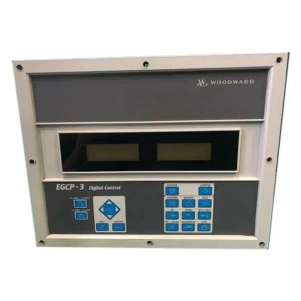
WOODWARD 8406-120
The Real-World Problem It Solves
Old-school generator controls relied on a rat’s nest of discrete relays, mechanical governor linkages, and separate synchronizing panels that took up half the control room. The Woodward 8406-120 condenses all of that into a single DIN-rail mounted package, handling everything from cranking logic and MPU speed sensing to precise load sharing and soft loading. It eliminates the nightmare of troubleshooting cascading relay logic when a genset fails to pick up load during a utility outage.
Where you’ll typically find it:
- In mission-critical standby power rooms (hospitals, data centers) managing automatic transfer schemes and utility paralleling.
- Inside offshore platform MCCs, controlling diesel drill rig generators and handling blackout recovery sequences.
- Bolted onto the skid of prime-power gas generators at remote pump stations, maintaining frequency stability under wildly fluctuating pipeline loads.
It replaces an entire cabinet of analog droop governors and isochronous load share amplifiers with a few kilobytes of deterministic code.
Hardware Architecture & Under-the-Hood Logic
This isn’t just a glorified PLC; it’s a purpose-built prime mover controller with the smarts to protect your engine and the finesse to balance megawatts. The onboard microcontroller continuously monitors system vitals and executes the control loop without waiting for a master controller to hold its hand.
- Signal Acquisition: The module takes high-voltage PT inputs and current transformer (CT) signals directly, scaling them to determine real and reactive power output. Simultaneously, it counts the MPU (Magnetic Pickup) pulses to derive engine speed with millisecond precision.
- State Machine Execution: Internal firmware runs the engine through deterministic state sequences (Crank, Fire, Sync, Load, Unload, Cooldown). It monitors lube oil pressure and coolant temperature to ensure the engine is viable before committing it to the bus.
- Closed-Loop Control: Based on the selected mode (Isochronous, Droop, or Base Load), the processor calculates the required actuator position or speed bias. It adjusts the PWM or analog output to the governor actuator, constantly trimming for deadbands and overshoot.
- Load Sharing Bus: It drives a ±3 V DC speed bias line that interconnects with other EGCP-2 units or analog load share governors. This analog tie-breaker allows multiple generators to split the load proportionally without needing constant digital comms.
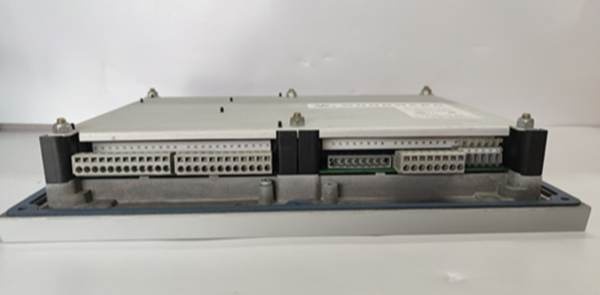
WOODWARD 8406-120
Field Service Pitfalls: What Rookies Get Wrong
Miswiring the CT Polarity on the Shared Bus
Rookies often treat Current Transformer (CT) wiring like a typical low-voltage signal, ignoring phase rotation. They hook up the CT secondaries backwards, and during a paralleling sequence, the 8406-120 thinks the generator is exporting reactive power when it’s actually importing it. This causes the unit to drive the generator into an over-excited state, tripping on over-voltage or, worse, blowing the main breaker.
- Field Rule: Before closing the generator breaker for the first time, perform a “fool’s loop” test. With the engine running uncoupled, force a small amount of reactive load via the control software. If the KVAR reading goes negative when you command positive, swap the CT leads. Always short the CT secondaries together before disconnecting the module to prevent dangerous flash arcs.
Ignoring the MPU (Magnetic Pickup) Air Gap
They assume the factory setting on the magnetic pickup sensor is gospel. Over time, gear teeth wear down or the sensor backs itself out due to vibration, increasing the air gap. The 8406-120 starts throwing intermittent “Loss of Speed Signal” faults, or the engine refuses to transition from crank to run because it can’t get a clean frequency reading.
- Quick Fix: If you see erratic RPM readings or sync failures, kill the prime power and check the MPU gap with a feeler gauge. It usually needs to be between 0.010″ and 0.020″. Clean the gear teeth of any debris or rust, and dielectric-grease the connector. A weak MPU signal is a leading cause of nuisance governor instability.
Forgetting to Save Configuration to Non-Volatile Memory
A rookie spends four hours online, tweaking the PID gains and droop settings to get the generator to stop hunting under load. Satisfied, he cycles the 24V DC power to the 8406-120 to clear a stray fault. The unit reboots and instantly reverts to the default factory parameters, causing the engine to surge violently when it picks up load again.
- Field Rule: Anytime you modify a tuning parameter, immediately execute the “Save to Flash” or “Store Configuration” command in the software. Treat RAM like it’s volatile—because it is. If the red FAULT light comes on after a power cycle, check the error log; it usually means the checksum failed and it dumped your changes.
Commercial Availability & Pricing Note
Please note: The listed price is for reference only and is not binding. Final pricing and terms are subject to negotiation based on current market conditions and availability.


