
Description
Hard Numbers: Technical Specifications
- Power Supply: 9–32 Vdc (12/24 Vdc nominal)
- Speed Sensing (MPU): 50–20,000 Hz input frequency
- Actuator Output: 0–200 mA (drives proportional actuators like Woodward EG-A, EG-3P)
- PT Input Voltage: 150–300 Vac (supports up to 30,000 kW gensets)
- CT Input: 5 A AC maximum
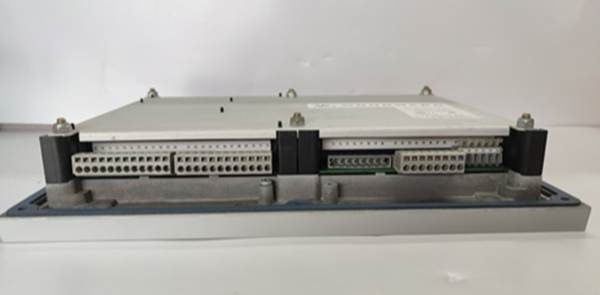
- Discrete Inputs: 16 channels (5 mA sinking current each, 80 mA total max)
- Analog Inputs: 1 channel (0–5 Vdc or 4–20 mA configurable)
- Voltage Bias Output: ±1 Vdc, ±3 Vdc, or ±9 Vdc
- Speed Bias Output: ±3 Vdc or 0.5–4.5 Vdc / 5V Peak 500 Hz PWM
- Relay Contacts: 10A @ 250 VAC resistive, 10A @ 30 VDC resistive
- Control Modes: Isochronous (0% droop) and adjustable droop (0-10%)
- Accuracy: ±0.25% of rated speed (isochronous mode)
- Communications: Modbus RTU/ASCII (RS-232/RS-485)
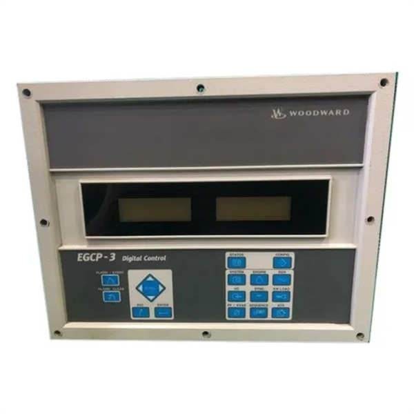
- Display: Two (2) backlit LCDs (8 lines x 20 characters)
- Operating Temperature: –20°C to +70°C (–4°F to 158°F)
- Vibration Standards: SV2 (5–2000 Hz @ 4 G), RV1 (10–2000 Hz @ 0.04 G²/Hz)
- Mounting: Panel mount or DIN rail
- Dimensions: Approx. 11.1″ W × 14.1″ H × 2.7″ D (282 × 358 × 69 mm)
- Weight: Approx. 7.8 lbs (3.54 kg)
The Real-World Problem It Solves
In industrial power generation and marine propulsion, maintaining stable frequency and voltage while seamlessly managing load transitions is a complex challenge. When a facility’s main utility power fails, or a ship’s load demand suddenly spikes, the onboard or backup generator must pick up the slack instantly and perfectly synchronize with the existing grid—or risk catastrophic damage to sensitive electronics and machinery. Manual synchronization is slow, imprecise, and dangerous.
The Woodward 8406-120 acts as the brain of the generator set, automating these critical transitions. It constantly monitors the generator’s output using a Magnetic Pickup (MPU) and Potential Transformer (PT) inputs. When it detects a frequency drop or a paralleling command, it instantly adjusts the engine’s throttle (via the actuator output) and manages the generator’s excitation (via voltage bias) to match the grid perfectly. Its built-in load-sharing logic ensures that when multiple generators are running in parallel, they split the electrical load proportionally, preventing any single unit from being overloaded .
Where you’ll typically find it:
- Data Centers & Hospitals: Providing seamless backup power transitions and stable frequency control for life-safety and IT systems .
- Marine Auxiliary Systems: Controlling thrusters, emergency generators, and main propulsion auxiliaries where precise speed and load sharing are vital .
- Industrial Microgrids: Managing multiple diesel/gas gensets in remote locations (mining, oil & gas) to optimize fuel consumption and extend engine life .
Hardware Architecture & Under-the-Hood Logic
The 8406-120 is a dedicated, stand-alone digital controller that tightly integrates engine speed control with generator electrical monitoring.
- Integrated MPU & PT Processing: Unlike basic governors that only look at engine speed, the 8406-120 simultaneously processes high-frequency MPU pulses (50-20,000 Hz) for instantaneous speed detection and PT/CT inputs for real-time kilowatt (kW) and reactive volt-ampere (kVAR) monitoring .
- Advanced PID Control Loop: The microprocessor executes fast, deterministic PID (Proportional-Integral-Derivative) algorithms. By comparing the target frequency (setpoint) and desired load percentage against the live MPU and PT/CT data, it calculates the exact 0-200mA output current needed to position the engine’s fuel actuator, ensuring deadbeat response with zero steady-state error .
- Autonomous Load Sharing: The unit features a dedicated load-sharing bus. In droop mode (typically 3-5%), multiple 8406-120 controllers can be connected in parallel without external communication cables. They naturally divide the total system load based on their individual droop settings. For tighter isochronous load sharing, they utilize Modbus communication to actively exchange real-time kW and kVAR data, making automatic adjustments to maintain perfect balance .
Field Service Pitfalls: What Rookies Get Wrong
Incorrect MPU (Magnetic Pickup) Air Gap Setting
The 8406-120 relies heavily on a clean, stable MPU signal to calculate engine speed. Rookies often install the MPU by simply tightening it down until it bottoms out against the flywheel gear, or they leave it too far away. If the air gap is too large, the signal amplitude drops, leading to “lost speed sense” faults during cranking. If it’s too tight, the vibration will eventually shear the MPU tip off, sending metal fragments into the gear mesh.
- Field Rule: Always use a feeler gauge to set the air gap precisely to the manufacturer’s specification (usually between 0.010″ and 0.025″). Never exceed the maximum torque specification when tightening the locknut, as over-tightening can warp the MPU housing and shift the sensing coil out of alignment .
Misunderstanding “Droop” vs. “Isochronous” in Parallel Systems
When bringing a new 8406-120 online in a multi-genset facility, inexperienced technicians often leave the unit in the default isochronous (0% droop) mode while attempting to parallel it with other running generators. This creates a “fight” for frequency control, resulting in severe load swing (hunting) where the generators alternately overload and underload each other.
- Quick Fix: For autonomous analog load sharing without a master controller, switch all paralleled units to “Droop” mode and set a small, identical droop percentage (e.g., 3-5%). This allows the generators to naturally settle into a stable load split. If isochronous operation is required, ensure all units are communicating via Modbus and that a proper isochronous load-sharing scheme is programmed in the software .
Neglecting Actuator Dither Settings
The 8406-120 outputs a 0-200mA signal to drive proportional fuel actuators (like the Woodward EG-A). Over time, carbon buildup and varnish in the actuator’s spool valve can cause it to stick, leading to sluggish throttle response. Rookies often blame the controller, but the issue is mechanical stiction.
- Field Rule: Enable and periodically adjust the “Actuator Dither” or “Jitter” function within the 8406-120’s configuration. Applying a small, high-frequency AC ripple (dither) to the DC control signal keeps the actuator’s internal spool valve microscopically vibrating, preventing it from sticking due to contamination or temperature changes .
Commercial Availability & Pricing Note
Please note: The listed price is for reference only and is not binding. Final pricing and terms are subject to negotiation based on current market conditions and availability.


