
Description
Hard-Numbers: Technical Specifications
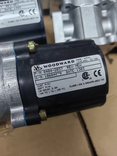
- Part Number: 8404-2037
- Rated Voltage: 24 VDC (Typical)
- Power Consumption: Approx. 40–60 W
- Control Signal: Analog position control (e.g., 4-20mA or 0-200mA dependent on driver configuration)
- Operating Temperature: -20°C to +70°C (-4°F to 158°F)
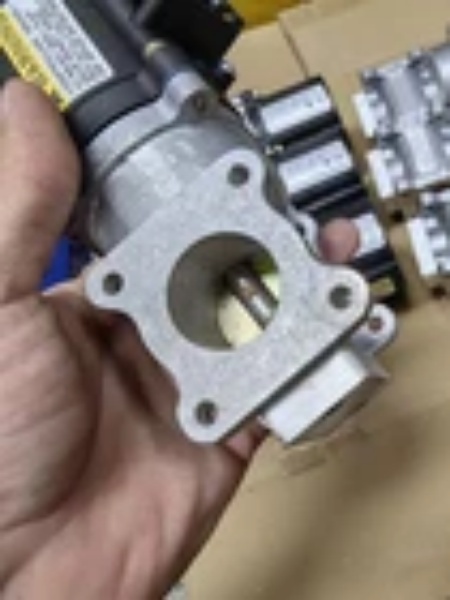
- Mounting Type: Flange / Direct coupling
- Dimensions (L×W×H): Approx. 280 × 180 × 200 mm (11.0 x 7.1 x 7.9 in)
- Weight: Approx. 8–12 kg (17.6–26.5 lbs)
- Protection Class: Industrial enclosure standard (varies by option, typically IP20 or housed)
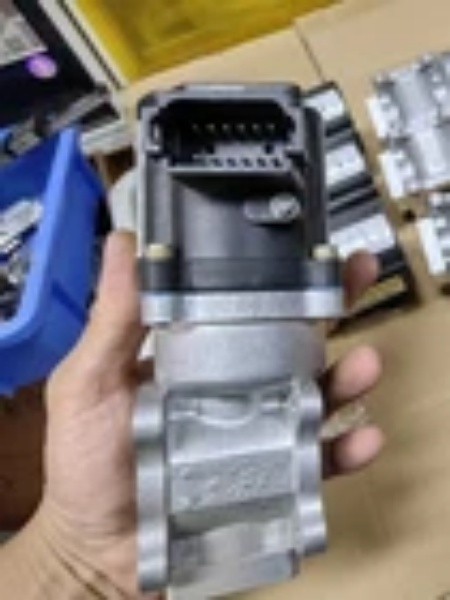
WOODWARD 8404-2037
The Real-World Problem It Solves
In industrial and marine propulsion engines, maintaining the optimal fuel-to-air ratio across varying loads and ambient conditions is critical for efficiency, emissions compliance, and preventing engine knock or surge. Manual or purely mechanical linkages are prone to wear, hysteresis, and thermal expansion, leading to sluggish response and inaccurate fuel metering.
Where you’ll typically find it:
- Mounted directly on the fuel control skid of a large marine diesel engine, dynamically adjusting the fuel rack position based on the governor’s demands.
- Integrated into the air-fuel ratio control loop of industrial gas turbines, where precise mixing is required to maintain combustion stability.
- Retrofitted onto legacy generator sets to replace worn-out pneumatic actuators, providing tighter control and reducing NOx emissions.
It translates low-power electrical control signals into high-force mechanical movement, ensuring the engine breathes and burns exactly as the digital governor intends.
Hardware Architecture & Under-the-Hood Logic
The 8404-2037 is a robust electromechanical device designed to withstand the harsh vibrations and thermal cycling of prime movers. While specific internal schematics can vary, UG25 series actuators generally operate on the following principles:
- Torque Motor / Solenoid Drive: An electrical current from the governor (e.g., 4-20mA) enters the valve’s torque motor or solenoid coil. This current generates a proportional magnetic field.
- Flapper/Nozzle or Spool Valve Mechanism: The magnetic field moves a flapper or pilot spool, which modulates the flow of high-pressure hydraulic fluid (or directly actuates a mechanical linkage in electric-only variants).
- Force Feedback Loop: As the output shaft moves, it tensions a feedback spring or rotates a cam. This mechanical force pushes back against the magnetic force. When the mechanical feedback perfectly balances the electromagnetic input, the valve stabilizes at that exact position.
- Damping and Stiction Compensation: Internal bypass orifices and precision-ground spools ensure that the valve responds quickly to small signal changes without oscillating, even under heavy load or低温 (low temperature) conditions.
WOODWARD 8404-2037
Field Service Pitfalls: What Rookies Get Wrong
Ignoring the Feedback Spring Preload During Installation
A common mistake is bolting the actuator to the engine linkage without properly accounting for the feedback spring preload. If the mechanical linkage is forced into position or the spring is compressed/extended beyond its calibrated range, the valve’s linear response curve is destroyed. The engine will run rich at low loads and lean at high loads.
- Field Rule: Never force the actuator arm. Always center the valve electrically (by applying a 12mA or 50% signal) before making the final mechanical connection to the fuel rack or throttle linkage. Verify the physical range of motion matches the electrical command range (0-100%).
Neglecting Hydraulic Supply Cleanliness (For Hydraulically-Assisted Units)
If the 8404-2037 relies on external hydraulic fluid pressure to assist with actuation, rookies often overlook the filtration requirements. Dirt particles as small as 10 microns can lodge in the pilot stage, causing the valve to stick or “dither” uncontrollably.
- Field Rule: Always install a 10-micron or finer filter in the hydraulic supply line dedicated to the actuator. Check the filter differential pressure gauge during routine maintenance. If the actuator response becomes sluggish, crack open the return line to check for excessive metal shavings or sludge.
Improper Electrical Shielding Leading to “Hunting”
Because this is an analog positioning device, it is highly susceptible to electrical noise. Technicians often run the 4-20mA signal wires in the same conduit as high-voltage starter motor cables or AC generator leads. The resulting EMF induces phantom voltage spikes on the signal line, making the valve hunt for its true position.
- Field Rule: Always use shielded twisted pair (STP) cable for the analog input. Ground the shield at the controller end ONLY. Keep the signal cables at least 12 inches away from high-current AC/DC power wires. If hunting persists, install a 500 Ohm resistor across the input terminals to dampen electrical ringing.
Commercial Availability & Pricing Note
Please note: The listed price is for reference only and is not binding. Final pricing and terms are subject to negotiation based on current market conditions and availability.


