
Description
Hard Numbers: Technical Specifications
- Operating Voltage: 24V DC (Standard industrial control voltage)
- Relay Contact Rating: 10A @ 240V AC
- Contact Form: SPDT (Single Pole Double Throw)
- Insulation Resistance: ≥ 1000 MΩ
- Operating Temperature: -40°C to +85°C (-40°F to +185°F)
- Relay Life Expectancy: ≥ 100,000 mechanical/electrical cycles
- Enclosure/Ruggedness Rating: IP65 (Dust-tight and protected against water jets)
- Physical Dimensions: Approx. 100mm x 60mm x 25mm / 72mm x 22mm x 17mm (Note: Enclosure dimensions vary slightly by specific sub-model/revision)
- Weight: Approx. 0.2 kg (200g)
The Real-World Problem It Solves
In heavy industrial automation, standard electronic sensors and solid-state controls can fail or lose calibration when exposed to extreme vibrations, moisture, or electrical noise. Furthermore, many legacy industrial systems (especially older turbine controls or large-scale HVAC units) rely on physical resistance changes (potentiometers) rather than digital signals to set operating parameters like fuel flow, damper position, or voltage regulation.
The Woodward 8271-756 bridges the gap between old-school reliability and modern precision. It acts as a robust, electrically adjustable variable resistor. When the control system sends a signal, an internal low-voltage motor physically drives a wiper along a resistive track to the exact desired position. Because the setting is mechanically held in place, it is highly resistant to electrical noise and vibration. If the main power fails, the mechanical position is retained, preventing dangerous system resets or uncontrolled state changes .
Where you’ll typically find it:
- HVAC & Building Automation: Controlling large industrial dampers, mixing boxes, and valve actuators where precise modulation is required .
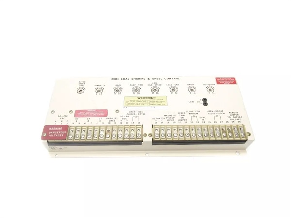
- Power Generation & Distribution: Used as a manual/auto-adjustment pot for voltage regulators or speed governors in older generator control panels .
- Industrial Machinery: Providing precise positional feedback or setpoint control for manufacturing equipment and heavy press brakes .
Hardware Architecture & Under-the-Hood Logic
Unlike a standard electromagnetic relay that simply clicks on or off, the 8271-756 is a sophisticated electromechanical positioning device.
- Motor-Operated Potentiometer Core: The heart of the device is a high-precision conductive plastic or wire-wound potentiometer coupled directly to a reversible electric motor (rated for 24V DC). When a control voltage is applied, the motor drives a gear train, moving the potentiometer’s wiper arm to vary the resistance .
- Limit Switch Integration: To prevent the motor from burning out or the wiper from breaking off the resistive track, the internal mechanism is equipped with physical limit switches. When the wiper reaches the extreme ends of its travel (0% or 100%), the limit switch disengages the motor drive, protecting the mechanics .
- SPDT Relay Isolation: The device integrates an SPDT relay (rated for 10A @ 240V AC) which is often used as a secondary control or feedback contact. This allows the potentiometer’s positioning motor to be completely electrically isolated from the circuit it is controlling, preventing ground loops and signal interference .
Field Service Pitfalls: What Rookies Get Wrong
Ignoring the Mechanical Limits During Bench Testing
Rookies often test the 8271-756 by applying 24V DC to the motor drive terminals without realizing the internal mechanics have reached their physical limit. If the potentiometer wiper is already at 0% (fully counter-clockwise) and voltage is applied to drive it further counterclockwise, the motor will stall.
- Field Rule: Always monitor the wiper resistance (check the datasheet for the pinout of the potentiometer terminals, usually the outer two pins are the fixed resistance and the middle is the wiper) with a multimeter while applying drive voltage. If the resistance stops changing but the motor is still humming, immediately remove the drive voltage to prevent overheating and damaging the internal gears.
Confusing the Motor Terminals with the Potentiometer Terminals
Under duress during a troubleshooting session, rookies often grab a multimeter and start probing the wrong terminals. They apply 24V DC to the potentiometer’s resistive element (thinking it’s the motor) or try to measure the resistance of the motor windings (thinking it’s the pot).
- Quick Fix: Look at the terminal block labeling carefully. The motor connections are typically separate from the 3-pin potentiometer strip. The motor will have a very low DC resistance (a few ohms), while the potentiometer will show a constant high resistance (e.g., 1kΩ, 5kΩ, or 10kΩ depending on the specific unit) between the two outer terminals regardless of its position.
Overlooking the SPDT Relay’s Role in the Control Loop
In many OEM drawings, the 8271-756 is not just a passive adjustable resistor; the internal SPDT relay is actively used in the control logic, often as a “limit reached” or “fault” contact. Rookies sometimes bypass this relay, wiring their control loops directly and ignoring the fact that the relay provides crucial isolation or safety feedback to the main PLC.
- Field Rule: Always trace the schematic for the SPDT relay contacts (Common, Normally Open, Normally Closed). Ensure the relay is receiving its operating coil voltage (often 24V DC) and that the contacts are not pitted or fused together, as this can send false signals to the main controller.
Commercial Availability & Pricing Note
Please note: The listed price is for reference only and is not binding. Final pricing and terms are subject to negotiation based on current market conditions and availability.


