
Description
Hard Numbers: Technical Specifications
- Operating Voltage: 18–32 V DC (24V DC Nominal)
- Power Consumption: ≤ 15W
- Speed Sensor Input: Magnetic Pickup (MPU), 1–30 Vrms, 2–10 kHz frequency range
- Speed Range: 500–15,000 Hz (depending on prime mover/gear ratio)
- Actuator Output: 0–200 mA DC (Current Drive) or PWM output
- Load Sharing Lines: ±3 V DC (for droop/isochronous load share)
- Analog Inputs: 2 Configurable (0–5 V DC or 4–20 mA)
- Digital Inputs: 6 (Configurable for Start/Stop, Mode Select, Raise/Lower)
- Digital Outputs: 4 (Alarm, Trip, Relay Control)
- Communication Interface: RS-232 (for configuration, monitoring, and Woodward Toolkit software)
- Operating Temperature: -40°C to +70°C (-40°F to +158°F)
- Enclosure/Protection: IP65 (when enclosed/panel mounted)
- Mounting: Panel or DIN Rail Mount
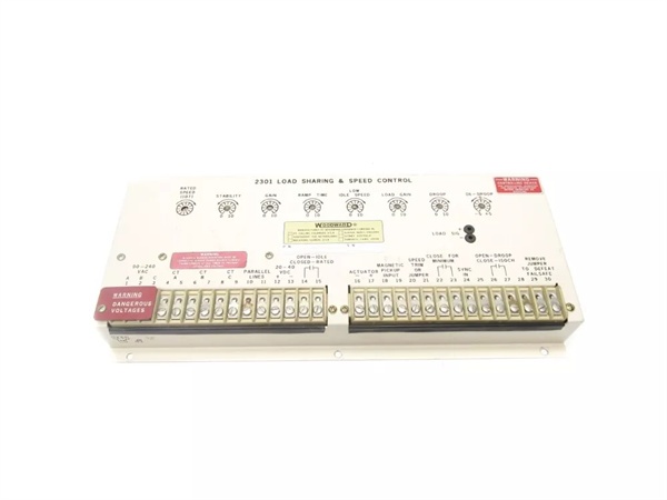
WOODWARD 8271-467
The Real-World Problem It Solves
Old-school mechanical flyweight governors are notoriously finicky—they drift with temperature changes, wear out mechanically, and make precise load sharing between multiple generators a nightmare. The Woodward 8271-467 digitizes the entire governing process. It takes the pulsing AC sine wave from your Magnetic Pickup (MPU), cross-references it with your selected control mode (like isochronous for stable frequency or droop for load sharing), and drives the actuator with pinpoint accuracy. It eliminates the “hunting” and steady-state drift of analog systems, keeping your prime mover locked in whether it’s carrying a steady base load or shifting dynamically in a microgrid.
Where you’ll typically find it:
- Generator Paralleling Panels: Managing multiple diesel or gas generators in power plants (utility or standby), ensuring fair and precise load distribution .
- Marine Propulsion Systems: Maintaining stable engine speed and load balance for ship main propulsion and auxiliary genets .
- Oil & Gas Facilities: Controlling compressor drivers or generator sets in remote oil fields and refineries .
- CHP (Combined Heat and Power) Plants: Balancing the electrical and thermal energy output demands .
Hardware Architecture & Under-the-Hood Logic
Don’t let its compact size fool you; the 8271-467 is a dedicated, high-speed industrial computer optimized for real-time control. It doesn’t run a heavy OS; it executes deterministic control algorithms in a continuous, fixed scan-time loop to guarantee zero-latency response during critical transients.
- Signal Conditioning & Speed Calculation: The front-end circuitry takes the raw, noisy AC waveform from the MPU, squares it up, and feeds it into a high-speed counter-timer. The DSP calculates the precise RPM in real-time.
- Control Law Execution: The core processor runs the loaded control strategy (configured via Woodward Toolkit). It computes the error between the actual speed/load and the setpoint, applying advanced PID loop compensation.
- Actuator Drive: Based on the PID output, the module generates a highly linear 0-200mA current drive (or PWM) to the connected actuator (e.g., EGB, ProAct, or throttle motor), constantly adjusting current to hold the setpoint.
- Load Sharing Bus Management: For multi-unit operations, it actively manages the 3V DC load sharing lines, communicating with peer units to proportionally distribute the total load based on each unit’s capacity and droop settings.
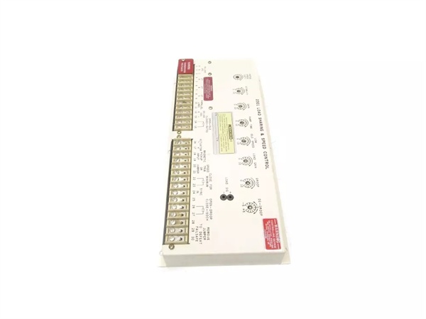
WOODWARD 8271-467
Field Service Pitfalls: What Rookies Get Wrong
Chasing Stability by Blindly Tweaking PID Gains
When a generator installation starts “hunting” (oscillating slowly around the target RPM), rookies immediately dive into the software and start cranking up the Proportional (P) gain or adding Derivative (D) terms. This often over-excites the actuator’s natural resonance, making the surging worse or causing mechanical wear.
- Field Rule: Before touching the PID gains, verify your mechanicals and sensing. Check the MPU gap—if it’s too large, the speed signal will be noisy. Ensure the actuator linkage isn’t sloppy or sticking. If the mechanics are tight, make small adjustments to the Integral (Reset) term first to eliminate steady-state droop.
Ground Loop Nightmares via Improper MPU Wiring
Rookies often treat the MPU (Magnetic Pickup) like a standard sensor, grounding the shield at both the module end and the pickup end. Because the 8271-467 measures frequency based on zero-crossings, any induced AC noise from nearby starters or poorly grounded generators will cause the speed reading to spike or drop erratically, leading to sudden load swings or nuisance overspeed trips.
- Quick Fix: Never double-ground your MPU shield. Connect the shield drain wire to the ground bus at the pickupend (or the module end, but strictly never both). Use a multimeter to check for phantom AC voltages between your signal common and the module ground. If you read more than 0.5V AC, you have a ground loop—fix the shielding immediately.
Ignoring the “Pickup Loss” Trip Settings During Comms Work
The 8271-467 has a vital safety feature: it can be programmed to trip the engine if the MPU signal is lost (Pickup Loss Detection). Rookies, while downloading new configurations or performing routine maintenance via the RS-232 port, accidentally disable this feature or change the sensitivity. If the MPU wire later vibrates loose during operation, the controller won’t trip, leading to an uncontrolled overspeed because the actuator goes to its fail-safe position too late.
- Field Rule: Any time you modify the GAP/Toolkit file and download it to the 8271-467, perform a “diff” check on the safety parameters (Overspeed, Underspeed, Pickup Loss). Verify that the Pickup Loss trip is enabled and set to a safe, non-zero RPM value before walking away from the panel.
Commercial Availability & Pricing Note
Please note: The listed price is for reference only and is not binding. Final pricing and terms are subject to negotiation based on current market conditions and availability.


