
Description
Hard Numbers: Technical Specifications
(Note: The following specifications are compiled from typical 8270-1058 operational parameters within the 8270 series. Please consult the official Woodward documentation for exact project engineering.)
- Part Number: 8270-1058 (Cross-refs: 8270-1061, DYN1-10784-000-0-12)
- Supply Voltage: 12 VDC / 24 VDC (Auto-sensing multi-range)
- Power Consumption: < 15W typical
- Speed Sensor Input: 2-channel Magnetic Pickup (MPU) compatible
- Speed Control Range: 100 – 10,000 RPM
- Control Accuracy: ±0.2% of rated speed
- Analog Inputs: 4–20 mA or 1–5 VDC (for speed/load setting)
- Analog Outputs: 0–10 V DC proportional output or 4-20mA
- Digital Outputs: Relay contact outputs (typically 250V AC / 5A)
- Communication Interface: RS-485 (Supports MODBUS RTU protocol)
- Operating Temperature: -40°C to +85°C (-40°F to 185°F)
- Protection Rating: IP20 (Chassis/Panel Mount)
- Dimensions (L x W x H): Approx. 200 mm × 150 mm × 50 mm (7.87″ × 5.91″ × 1.97″)
- Weight: Approx. 1.2 kg (2.65 lbs)
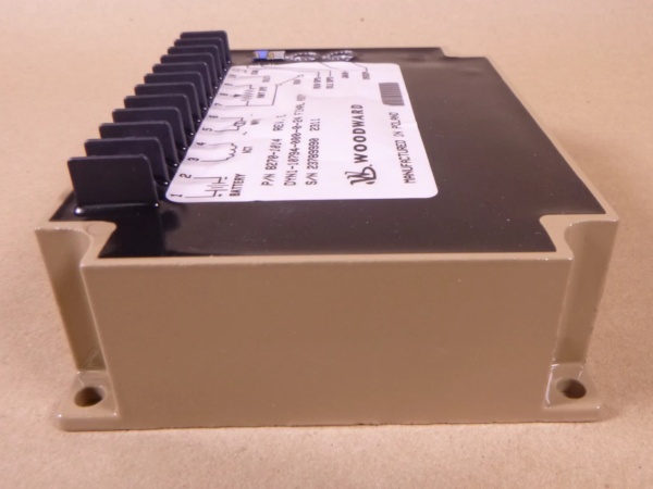
Woodward 8270-1014
The Real-World Problem It Solves
Imagine a remote offshore oil platform or a busy data center relying on diesel generator sets for primary or backup power. When a massive load—like a large motor or HVAC system—kicks in, the sudden demand can cause the generator’s engine to bog down, dropping its RPM and frequency. This fluctuation can trip sensitive servers, damage heavy machinery, or cause blackouts. Conversely, if the load suddenly drops, the engine might overspeed, leading to catastrophic mechanical failure or fire risks.
The Woodward 8270-1058 acts as the “digital brain” of the engine’s fuel system. It constantly monitors the engine’s instantaneous RPM via a Magnetic Pickup (MPU) sensor. When it detects the slightest deviation from the target speed, its internal 32-bit processor executes a high-speed PID (Proportional-Integral-Derivative) loop, calculating the exact correction needed. It then instantly adjusts the analog or PWM output to the fuel actuator, meticulously modulating the fuel rack to bring the speed back to equilibrium—all within milliseconds .
Where you’ll typically find it:
- Diesel Generator Sets: Providing prime power or standby power in hospitals, data centers, and industrial plants .
- Marine Propulsion: Controlling main propulsion diesel engines or auxiliary generators on cargo ships and offshore vessels .
- Oil & Gas Compression: Regulating gas turbine or diesel engine speeds in remote pipeline compressor stations .
Hardware Architecture & Under-the-Hood Logic
Unlike older analog governors that rely on unstable RC timing circuits, the 8270-1058 is built around a modern, high-speed 32-bit RISC microcontroller, making it highly programmable and precise.
- Signal Conditioning & MPU Interface: The module accepts input from a 2-wire Magnetic Pickup (MPU) installed near the engine flywheel. Internally, the incoming sine wave is conditioned, filtered for noise, and converted into a stable square wave. The microcontroller’s high-speed counter then calculates the exact frequency (RPM) in real-time .
- The PID Control Algorithm: The core of the 8270-1058 is its digital PID loop. The microcontroller continuously compares the actualRPM to the desiredRPM (set via the analog input or communication link). It calculates the error value and, using tuned Proportional, Integral, and Derivative terms, determines the exact actuator position required to eliminate the error without causing oscillation (“hunting”) .
- DAC & Output Driving Stage: Once the PID loop determines the required fuel position, the microcontroller sends a digital command to a high-resolution Digital-to-Analog Converter (DAC). This generates a precise voltage or current signal (0-10V or 4-20mA) which is then amplified by the output driver stage to directly control the Woodward EFC actuator or electronic fuel injection system .
- Protection & Watchdog Logic: An independent hardware watchdog timer monitors the main microcontroller. If the software crashes or hangs due to an electrical anomaly, the watchdog will force the output drivers to a predefined safe state (e.g., returning the actuator to a mechanical idle stop) to prevent an overspeed condition .

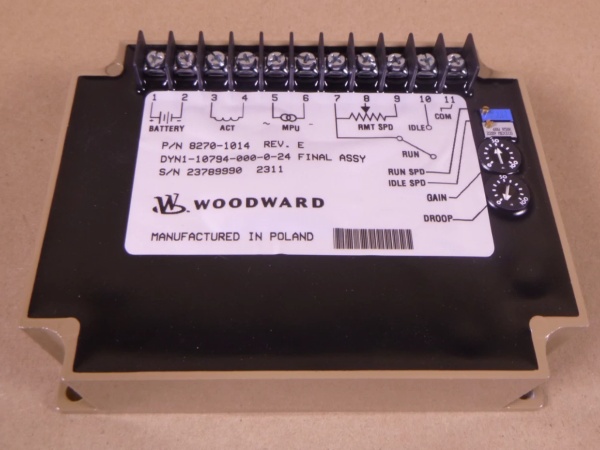
Woodward 8270-1014
Field Service Pitfalls: What Rookies Get Wrong
Incorrect MPU (Magnetic Pickup) Air Gap
Rookies often install the MPU (speed sensor) by simply tightening it until it bottoms out against the flywheel gear, or leaving it too far away.
- The Glitch: The MPU generates its voltage based on the magnetic flux cutting across the coil as the gear teeth pass. If the air gap is too large, the generated voltage at cranking speeds will be too low for the 8270-1058 to detect, causing a “Loss of Speed Signal” fault and preventing the engine from starting. If it’s too tight, vibration can destroy the sensor, or metal shavings can magnetize and ruin the reading .
- Field Rule: Always use a feeler gauge. Woodward typically specifies an air gap between 0.010″ and 0.060″ (0.25mm – 1.5mm) depending on the specific MPU model. Rotate the engine to ensure the gap is consistent across all gear teeth.
Ground Loop Induced PID Instability (Hunting)
Because the 8270-1058 relies on precise analog measurements and high-speed digital processing, it is highly susceptible to ground loops.
- The Consequence: If the 8270-1058’s 0V (common) is connected to earth ground at the module, and the DCS (Distributed Control System) or actuator it talks to is grounded at a different potential hundreds of feet away, a circular current path (ground loop) is formed. This introduces a 50/60Hz AC ripple into the DC speed signal, tricking the PID loop into thinking the speed is oscillating. The controller will then violently “hunt,” constantly over-correcting the fuel actuator .
- Field Rule: Use a single-point ground system. Connect the 8270-1058’s 0V common to earth ground at the power supply terminal only. Ensure all shielded cables (MPU, 4-20mA) have their shields drained to ground at the source end exclusively.
Ignoring “Derivative” Gain During Commissioning
When first commissioning the 8270-1058, rookies often dial in the Proportional (P) and Integral (I) gains to get the engine to stabilize, but they leave the Derivative (D) gain at zero.
- The Danger: Without Derivative action, the governor only reacts to how far offit is (P) and how longit has been off (I). When a massive step-load is applied (e.g., a large motor starter kicking in), the initial RPM drop is massive. Without “D” (which predicts the future error based on the rate of change), the actuator will respond sluggishly, causing the engine to dip severely in frequency before recovering. In extreme cases, this can stall the generator .
- Field Rule: After setting P and I, slowly increase the Derivative gain while observing the engine’s response to a simulated load step. The goal is to get the actuator to anticipatethe load drop and open the fuel rack preemptively. Stop increasing D once the engine recovers quickly without oscillating.
Commercial Availability & Pricing Note
Please note: The listed price is for reference only and is not binding. Final pricing and terms are subject to negotiation based on current market conditions and availability.


