
Description
Hard Numbers: Technical Specifications
- Operating Voltage: 20–32 VDC (24 VDC nominal)
- Peak Power Consumption: 95 W (Max draw during transient response)
- Recommended Charging System: Minimum 5 A continuous capacity
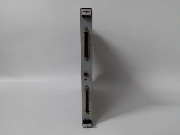
- Speed Sensor Input: Compatible with Magnetic Pickup (MPU) or VR sensors
- Actuator Output Shaft: 0.375″-36 SAE serrated (dual-ended)
- Maximum Output Torque: High-torque design to overcome stiff return springs
- Work Output: 2.3 Joules (1.7 ft-lb) per operation cycle
- Operating Temperature: -40°C to +93°C (-40°F to +200°F)
- Circuit Protection: Requires external 10 A slow-blow fuse
- Maximum MPU Wire Length: 23 m (75 ft) using 12 AWG wire
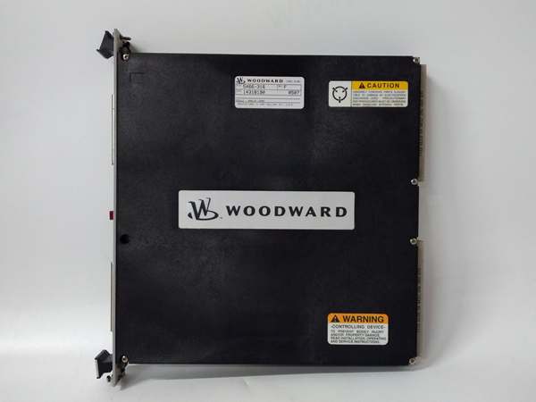
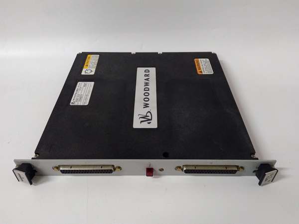
WOODWARD 5466-031
The Real-World Problem It Solves
Mechanical flyweight governors wear out. Their pivot points get sloppy, causing speed drift and hunting. When you need precise speed control on a standby generator or a remote compressor station, a mechanical governor is a liability. The 8256-916 replaces that aging mechanical linkage with a responsive electronic closed-loop system. It takes the headache out of engine tuning and stabilizes your prime mover against load transients.
Where you’ll typically find it:
- Bolted directly to the side of a large diesel generator set, replacing the original mechanical governor to improve load acceptance.
- Controlling the fuel rack on gas lift compressors in remote oil fields where maintenance access is limited.
- Retrofitted onto marine auxiliary engines to provide tighter speed regulation and integration with modern alarm systems.
It eliminates the mechanical slack in your fuel system and gives you a tight, repeatable RPM lock.
Hardware Architecture & Under-the-Hood Logic
This unit is a self-contained control loop. It doesn’t need a separate PLC to tell it what to do; it reads the engine speed directly and drives the actuator.
- Frequency Acquisition: The module takes the sine wave input from the Magnetic Pickup (MPU) sensor, conditions the signal, and converts it into a stable RPM reading.
- Error Calculation: It continuously compares the actual RPM against the internally set “Rated Speed.” The difference is the speed error.
- PID Compensation: A dedicated analog/digital hybrid circuit processes the error signal using Proportional, Integral, and Derivative (PID) logic. This calculates exactly how far and how fast the actuator needs to move to correct the speed.
- H-Bridge Motor Drive: Based on the PID output, an internal H-Bridge circuit fires the 24V DC motor in the actuator, driving the output shaft to increase or decrease fuel until the RPM error is zero.
WOODWARD 5466-031
Field Service Pitfalls: What Rookies Get Wrong
MPU (Magnetic Pickup) Air Gap Settings
Rookies install the speed sensor using the “finger tight plus a quarter turn” method. If the gap between the sensor tip and the gear teeth is too wide, the voltage signal drops, especially at low cranking speeds. The controller loses track of the RPM, assumes a runaway condition, and slams the fuel to zero, causing a failed start.
- Field Rule: Use a multimeter. Crank the engine (fuel off) and measure the AC millivoltage at the MPU terminals. Adjust the sensor in or out until you see a clean, strong sine wave, typically between 1.5V and 5V AC at cranking speed. Lock it down and recheck.
Voltage Sag During Transient Loads
The 8256-916 pulls significant current when the actuator motor kicks in to counter a sudden load step. Rookies tap into a shared 24V bus that also powers solenoids and indicator lights. When a large contactor pulls in, the voltage at the 8256-916 dips below 20V. The module interprets this as a power loss, resets, and drops the actuator to the “fuel off” position.
- Quick Fix: Run a dedicated 10AWG (or larger) pair directly from the battery terminals or a dedicated power distribution block to the 8256-916. Install a 10A slow-blow fuse in the positive lead right at the power source. Do not share this fuse with anything else.
Ground Loop Feedback Errors
In metal enclosures, rookiеs get lazy with grounding. They bond the 24V negative to the chassis in multiple locations. When the starter motor engages, hundreds of amps flow through the engine block, creating a voltage potential difference between the battery ground and the controller ground. This back-feeds through the actuator control loop, tricking the PID into thinking the actuator is moving when it isn’t.
- Field Rule: Use a single-point ground strategy. Connect the 24V negative and the actuator chassis ground to the same stud on the engine block. Keep your sensor shields isolated at the controller end and grounded only at the sensor end to kill electromagnetic interference.
Commercial Availability & Pricing Note
Please note: The listed price is for reference only and is not binding. Final pricing and terms are subject to negotiation based on current market conditions and availability.


