
Description
Hard Numbers: Technical Specifications
(Note: Exact specifications can vary. The following represents typical data for the Woodward 0250 / 8250 series 12V actuators. Always verify against your specific engine’s service manual.)
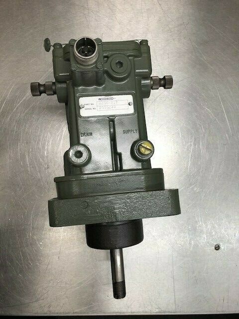
- Part Number: 8250-1502
- Alternate Part Number: 0250-12A2UC11S3
- Voltage Rating: 12 VDC
- Current Draw (Nominal): ~2.5 – 5.0 Amps (holding current typical for Woodward pull-type solenoids)
- Duty Cycle: Intermittent (Pull-in) / Continuous (Holding)
- Connection Type: Threaded hydraulic/mechanical linkage (specific to engine fuel pump/rack)
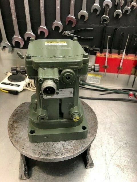
- Enclosure/Housing: Industrial-grade metal casing with corrosion-resistant coating
- Operating Temperature: -40°C to +85°C (-40°F to 185°F) typical
- Mounting Orientation: Direct bolt-on to engine fuel injection pump or shutoff mechanism
The Real-World Problem It Solves
In industrial power generation and heavy machinery, you never want an engine to slowly wheeze to a halt. When a critical fault occurs—such as low oil pressure, high coolant temperature, or an overspeed event—the engine needs to cease fuel delivery instantlyto prevent catastrophic mechanical failure. Similarly, during a scheduled shutdown, you need a controlled, predictable way to cut power. Relying purely on electronic throttles to shut down can be risky if there’s a loss of control signal.
The Woodward 8250-1502 acts as the ultimate mechanical “break glass in case of emergency” device. Mounted directly to the engine’s fuel injection pump or throttle linkage, this 12V solenoid is normally configured as a “fail-safe” or “pull-to-stop” actuator. In its de-energized state, it physically holds the fuel rack in the idle or shutdown position. When the engine needs to run, the controller sends 12VDC to the solenoid, generating a powerful magnetic field that pulls the plunger, allowing the mechanical governor to control the fuel rack. If the 12V signal is lost (either intentionally for a shutdown or due to a system failure), the solenoid immediately releases, and the engine’s internal springs snap the fuel rack back to the zero-fuel position, bringing the engine to a rapid, safe halt .
Where you’ll typically find it:
- Cummins Generator Sets: Directly mounted on the fuel injection pump of engines like the C110D5, acting as the primary electrical shutdown device .
- Industrial Fire Pump Engines: Serving as the NFPA-required remote manual shutdown actuator.
- Off-Road Heavy Equipment: Providing emergency stop capabilities for construction and mining machinery diesels.
Hardware Architecture & Under-the-Hood Logic
Unlike the complex digital controllers we’ve discussed previously, the 8250-1502 is a beautifully simple yet robust example of pure electromechanics.
- The Pull-Type Electromagnet: At its core, the unit consists of a high-grade copper coil wound around a hollow steel bobbin. When 12VDC is applied to the terminals, current flows through the coil, generating a strong electromagnetic field.
- The Plunger & Linkage: Inside the bobbin sits a hardened steel plunger (or armature) attached to a stainless steel push/pull rod. This rod mechanically interfaces with the engine’s fuel control rack. When the coil is energized, the magnetic field pulls the plunger sharply upwards into the coil’s center, overcoming the tension of the fuel shutoff spring. This movement shifts the fuel rack into the “run” or “active” position .
- Continuous Duty Holding: Once the plunger is fully seated, the electromagnetic field only needs to maintain a fraction of the initial pull-in current to keep the plunger in place. This allows the solenoid to remain energized for extended periods (continuous duty) without overheating, ensuring the engine runs smoothly until a shutdown is commanded .
Field Service Pitfalls: What Rookies Get Wrong
Incorrect Linkage Adjustment (The “Bound” Plunger)
Rookies often bolt the solenoid to the engine and call it a day, but the mechanical adjustment between the solenoid plunger and the fuel pump rack is critical. If the solenoid is mounted too close, the plunger won’t have enough travel to fully seat, causing the engine to die under load. If it’s mounted too far away, the plunger will bottom out inside the coil, generating excessive heat and preventing the fuel rack from returning to the idle position.
- Field Rule: Always use the specified feeler gauges or adjustment nuts (depending on the specific engine model) to set the proper plunger clearance (often called “solenoid stroke” or “linkage free play”). Manually cycle the solenoid and watch the fuel rack move freely through its full range of motion before locking down the mounting bolts .
Ignoring the Flywheel Effect (Voltage Drop on Crank)
When a large diesel engine cranks, it draws massive amperage from the starting batteries. This can cause the battery voltage to sag well below 12V (sometimes dropping to 9V or 8V during cold weather starts). Rookies assume that if the solenoid clicks once, it’s getting enough power. However, a weak battery or undersized wiring can cause the voltage at the solenoid terminals to drop below the “pull-in” threshold during cranking, causing the solenoid to release and killing the engine right as it’s trying to start.
- Quick Fix: During installation, always run a dedicated, appropriately sized power cable (e.g., 10-gauge or thicker) directly from the battery or a solid 12V bus bar to the solenoid, bypassing any shared fuse blocks or thin control wires. Check the voltage at the solenoid terminals while the engine is cranking. If it drops below 9VDC, you have a wiring or battery issue that needs to be resolved .
Installing It Upside Down (Gravity vs. The Plunger)
It sounds silly, but in the heat of a midnight breakdown, rookies frequently misread the mounting orientation. Woodward solenoids like the 8250-1502 are designed to be pulled “up” against gravity. If installed upside down, the heavy steel plunger has to fight gravity to seat properly. Over time, this extra strain fatigues the coil, leading to intermittent shutdown failures.
- Field Rule: Look for the “TOP” stamp on the solenoid housing or refer to the engine diagram. Ensure the solenoid is mounted in the orientation specified by the engine manufacturer to guarantee reliable operation .


