
Description
Hard Numbers: Technical Specifications
- Operating Voltage: 20–32 VDC (24VDC or 32VDC nominal system voltage)
- Maximum Output Current: 1.5 A to 3.0 A (depending on connected servo/oil motor inductance)
- Command Input Range: 0–5 VDC, 0–10 VDC, or 4–20 mA (jumper selectable for 2301 governor interfacing)
- LVDT Excitation: 3.0 VAC to 24 VAC RMS (typically 60 Hz or 400 Hz derived from system supply)
- LVDT Feedback Input: Supports single or dual redundant LVDTs (0–135 VAC RMS range)
- Isolation Rating: 500 VDC minimum (Control inputs isolated from actuator power output)
- Operating Temperature: -40°C to +70°C (-40°F to +158°F)
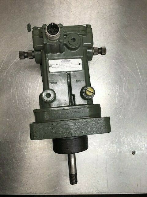
- Physical Mounting: Flange mount with 4 corner-drilled installation holes for direct integration into hydraulic skids or control cabinets.
The Real-World Problem It Solves
Your main turbine governor (like a 2301 series) is brilliant at calculating RPM and droop, but it can’t physically push a heavy hydraulic valve or spin a high-torque oil motor. The 8250-010 acts as the brawn behind the brains. It takes the weak analog command from the governor, isolates it from the electrical noise of the plant floor, and amplifies it into a high-current drive signal that actually has the guts to move heavy industrial actuators.
Where you’ll typically find it:
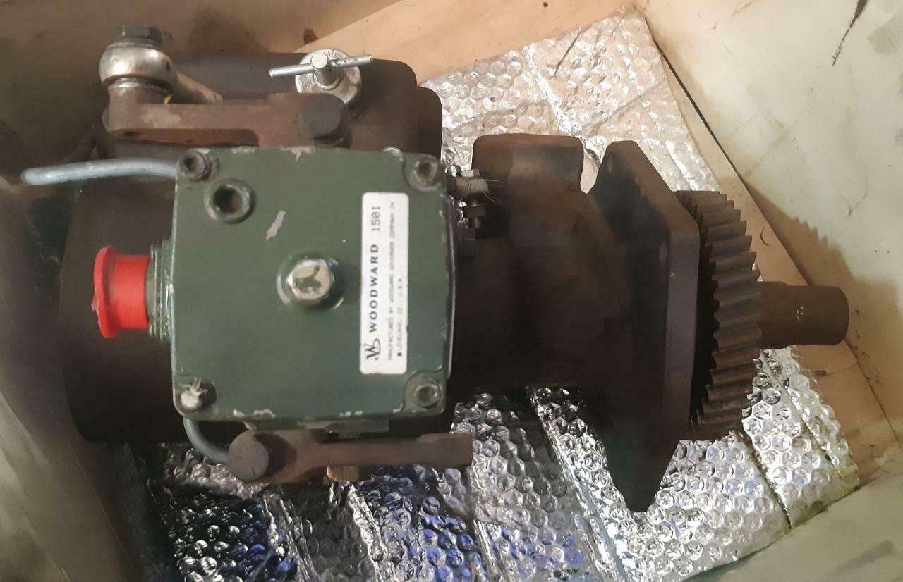
- Bolted to the side of an EG-3P hydraulic actuator assembly, driving the main fuel stroke control on older diesel generators.
- Mounted in the local control cabinet of a small steam turbine, interfacing the mechanical-hydraulic governor to modern electronic controls.
- Retrofitted into compressor stations to provide a bridge between a new DCS and the existing legacy fuel gas valves.
It saves you from having to replace the entire turbine control architecture just to fix a burnt-out valve driver.
Hardware Architecture & Under-the-Hood Logic
Forget microprocessors and firmware updates; the 8250-010 is old-school analog engineering at its finest. It’s built around a straightforward closed-loop control topology designed for maximum uptime.
- Signal Conditioning: The incoming command signal (from the 2301 governor or DCS) first passes through an isolation stage to strip out any common-mode noise picked up from nearby VFDs or contactor coils.
- Error Amplification: A precision operational amplifier continuously compares the conditioned command signal against the actual valve position (fed back by the LVDT). The difference between the two generates a highly sensitive error signal.
- Push-Pull Output Stage: This error signal drives a robust transistorized output stage. Because it’s a linear amplifier, it can source or sink current smoothly, preventing the jerky, step-wise movements that plague cheaper PWM drivers.
- LVDT Demodulation: An internal precision rectifier converts the AC feedback from the LVDT into a stable DC voltage, presenting a clean position signal back to the governor for monitoring.
Field Service Pitfalls: What Rookies Get Wrong
Chasing “Valve Hunting” Without Checking the Bushings
When an actuator starts oscillating around its setpoint (hunting), rookiеs immediately blame the PID gains in the governor. They spend hours tweaking software parameters while ignoring the fact that the 8250-010 is just faithfully amplifying the mechanical slop in the system.
- Field Rule: If the valve is hunting, kill the power and physically check the actuator’s linkage and the 8250-010’s internal compensation bushings. After decades of service, these bushings wear out, introducing mechanical deadband. The electrical signal might be perfect, but the valve can’t translate that into smooth movement. Replace the worn hardware before touching the gains.
Ignoring Internal Seal Degradation in Hydraulic Integrators
The 8250-010 is often paired with hydraulic pilot valves or integrators. Rookies treat the electrical driver as a black box and ignore the hydraulic side of the assembly. Over time, the internal O-rings and seals dry out and crack. The result is internal leakage past the pilot spool. The 8250-010 will drive the output to 100% trying to reach the commanded position, but the actuator won’t move because the hydraulic pressure is bleeding off.
- Quick Fix: If you command a slow, steady valve movement and the 8250-010’s output current climbs to its maximum limit without the valve actually moving, you don’t have an electrical problem—you have a hydraulic leak. Rebuild the pilot valve assembly and replace the seals.
Letting Corrosion Sit on the Terminal Blocks
Because the 8250-010 is usually mounted close to the actuator (and sometimes outdoors), the terminal blocks are exposed to vibration, temperature swings, and moisture. Rookies tighten a loose wire, see that the system works, and walk away. Six months later, galvanic corrosion has turned the copper strands into green dust, causing intermittent signal dropouts.
- Field Rule: During every outage, pull the wires off the 8250-010 terminals. If you see any green oxidation on the copper lugs, cut the wire back to fresh metal, re-crimp a new terminal, and apply dielectric grease before re-terminating. Check the torque on the mounting bolts too; a loose ground lug here will cause phantom trips in your governor.
Commercial Availability & Pricing Note
Please note: The listed price is for reference only and is not binding. Final pricing and terms are subject to negotiation based on current market conditions and availability.


