


Description
Hard Numbers: Technical Specifications
- Supply Voltage: 18-32 V DC (24V DC Nominal)
- Actuator Drive Output: Configurable ±10 mA to ±250 mA (supports various valve coil impedances)
- Position Demand Input: 4-20 mA Analog or DeviceNet Digital Network
- Feedback Input: Compatible with LVDT, RVDT, or DC Transducers
- Output Resolution: 11 Bits
- Communication Ports: DeviceNet, RS-232 (Service/Config Port)
- Operating Temperature: -40°C to +70°C (-40°F to +158°F)
- Power Dissipation: 20W Typical Heat Load
- Inrush Current Protection: Requires 5A, 125V Fuse (20A for 100ms inrush rating)
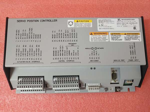
Woodward 8200-226
The Real-World Problem It Solves
Old turbine fuel racks and steam admission valves rely on incredibly tight positioning tolerances. If your fuel valve overshoots by even a few percent, you risk tripping the generator on overspeed or, conversely, failing to pick up load. The Woodward 8200-226 acts as the muscle and the brain for your final control elements. It takes the sometimes noisy 4-20mA demand signal from your DCS or MicroNet, scrubs it, and drives the servo valve coil with dead-accurate current while constantly cross-checking the actual stem position via LVDT feedback.
Where you’ll typically find it:
- Mounted inside the local control cabinet of a GE or Siemens heavy-duty gas turbine, managing the liquid fuel bypass valve or gas fuel control valve.
- In steam turbine packages, controlling the steam admission valves (MSV/CRV) for precise speed and load regulation.
- On compressor skids in pipeline applications, driving anti-surge valve actuators to prevent aerodynamic stall.
It eliminates the sloppy hysteresis of old analog positioners and provides a tight, closed-loop control system that keeps your turbine from hunting or surging.
Hardware Architecture & Under-the-Hood Logic
This isn’t just a dumb amplifier; it’s a dedicated motion controller. It features a robust microcontroller that handles the demanding math of closed-loop PID control and signal conditioning in real-time.
- Command Acquisition: The module accepts a position demand either via a standard 4-20mA analog loop or a DeviceNet network packet. Internally, it filters this demand to remove electrical noise.
- Feedback Comparison: It simultaneously energizes and reads the return signals from up to two redundant LVDTs (Linear Variable Differential Transformers) or RVDTs. It compares the averaged, scaled feedback voltage against the filtered demand signal to calculate a precise error value.
- PID Calculation & Output Drive: The embedded PID algorithm processes the error value. To prevent valve stem “dither” or hunting, the processor adjusts the duty cycle of the output driver stage, supplying the exact current needed to move the valve to the commanded position.
- Health Monitoring: The onboard diagnostics constantly monitor the loop. If the valve doesn’t move to the expected position within a set time, or if an LVDT fails, it triggers a watchdog fault and can safely ramp the valve to a predetermined fail-safe position.
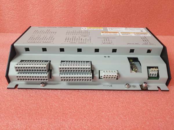
Woodward 8200-226
Field Service Pitfalls: What Rookies Get Wrong
Botching the LVDT Phase Alignment (The “Out-of-Phase” Disaster)
Rookies wiring up a replacement 8200-226 often treat the LVDT feedback wires like a standard DC potentiometer. They hook up the excitation and sense coils randomly. When the controller tries to close the valve, the out-of-phase LVDT signal tells the processor the valve is opening. The PID loop then goes into a death spiral, slamming the valve fully open or closed, often resulting in a loud mechanical crunch or a turbine trip.
- Field Rule: Never guess on LVDT phasing. Use a signal generator and a voltmeter. Energize the LVDT primary, then check the secondary outputs. Swap the secondary wires if the voltage decreases when you expect it to increase. Always perform a slow, manual 0-100% stroke test while watching the feedback curve on the Woodward service software before putting the loop in automatic.
Ignoring the Jumper Settings for Dual Redundant Feedback
In critical turbine applications, we wire two LVDTs for redundancy. Rookies assume the 8200-226 automatically averages them. They fail to set the correct hardware jumpers or software DIP switches to configure the module for “Dual LVDT” mode. The controller defaults to reading only one feedback channel. When that single LVDT inevitably fails six months later, the control loop breaks, and the turbine trips offline.
- Quick Fix: Go into the SPC service tool software. Check the “Feedback Status” bits. If you see a massive deviation between LVDT A and LVDT B readings, your jumpers are wrong, or one of your feedback arms has slipped on the valve stem. Fix the mechanical linkage or correct the jumper configuration immediately.
Undersizing the Fuse and Ignoring Inrush
The 8200-226 drives inductive loads (solenoids and servo valves). When that valve snaps shut, the collapsing magnetic field sends a voltage spike back into the module. Rookies install a standard 5A fast-blow fuse. The first time the valve moves aggressively, the inrush or back-EMF pops the fuse, killing the positioner and causing a controlled shutdown.
- Field Rule: Respect the power requirements. The manual specifies a 5A fuse with a 20A/100ms inrush withstand rating for a reason. Use a time-delay (slow-blow) fuse or a properly sized circuit breaker. If you keep blowing fuses, check your servo valve coil for an intermittent short to ground, not just the fuse rating.
Commercial Availability & Pricing Note
Please note: The listed price is for reference only and is not binding. Final pricing and terms are subject to negotiation based on current market conditions and availability.


