
Description
Hard-Numbers: Technical Specifications
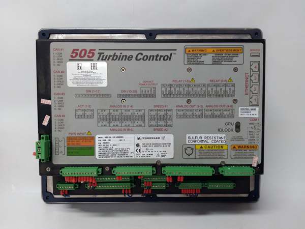
- Part Number: 8200-1331
- Product Series: 505DR (Dual Redundant)
- Power Supply: HVAC/DC (88–264 VAC / 90–150 VDC)
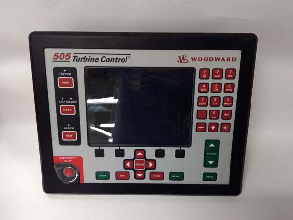
- User Interface: 8.4-inch Multilingual Color Graphical LCD
- Control Loops: Advanced PID with OptiTune™ adaptive control capabilities .
- Speed Sensor Inputs: Supports redundant MPUs and proximity sensors .
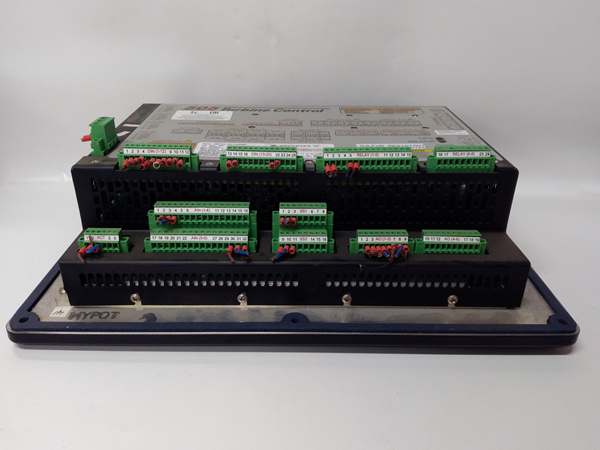
- Analog I/O: 8 Inputs (4–20 mA), 6 Outputs (4–20 mA) .
- Discrete I/O: 20 Configurable Contact Inputs, 8 Form-C Relay Outputs .
- Communication Ports: 4 x Ethernet (Modbus TCP/OPC), 4 x CANOpen, 1 x RS-232/422 .
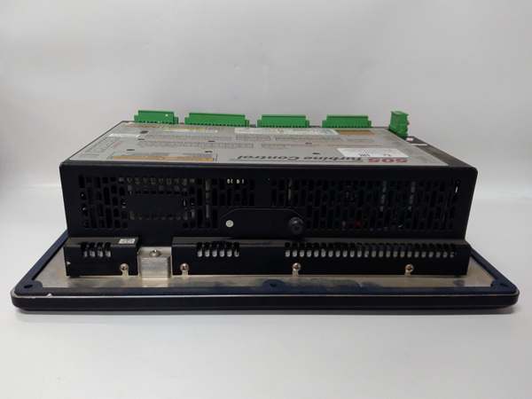
- Mounting Style: Panel Mount .
- Operating Temperature: –30°C to +70°C .
- Environmental Rating: Ordinary Location; Class G3 Conformal Coating .
WOODWARD 8200-226
The Real-World Problem It Solves
In critical infrastructure—such as combined heat and power (CHP) plants, oil refineries, or chemical processing facilities—a turbine trip doesn’t just mean a loss of power; it means flaring gases, shutting down exothermic reactions, or losing millions in revenue per hour . Traditional simplex governors represent a single point of failure. The Woodward 8200-1331 eliminates this risk through its dual-redundant (505DR) architecture. By mirroring all logic and state-changes to a secondary “hot-standby” unit via a Real-Time Network (RTN), it guarantees bumpless, ultra-fast failovers. This ensures the turbine keeps running even if a processor, power supply, or communication card fails mid-operation .
Where you’ll typically find it:
- Bolted to the control cabinet of a critical extraction steam turbine in a petrochemical plant where 24/7 stability is non-negotiable .
- Serving as the primary redundant governor for large-scale CHP turbines supplying both electricity and district heating .
- Managing steam turbines driving high-speed compressors in refineries to prevent catastrophic process upsets .
Hardware Architecture & Under-the-Hood Logic
The 8200-1331 is engineered as a fault-tolerant industrial computer, specifically designed to survive the electrical and mechanical stresses of heavy rotating equipment .
- Dual-Redundant Core Processing: The controller operates as a Master/Slave pair. Both units constantly synchronize their internal databases. If the Master unit detects an internal fault, a hardware-level switch occurs instantaneously, promoting the Slave to Master without dropping the valve command signals .
- OptiTune™ Adaptive Algorithms: Instead of relying on static PID gains, the 8200-1331 dynamically adjusts its control parameters based on real-time turbine load and process variables. This eliminates the “hunting” or prolonged settling times typically seen during large load rejections or sudden steam header pressure swings .
- Comprehensive I/O Scanning: With 8 analog inputs, 6 analog outputs, and 20 discrete inputs, the module handles everything from LVDT valve position feedback to emergency lube oil pressure switches. The I/O is conditioned to reject electrical noise from nearby VFDs and high-voltage switchgear .
- High-Voltage Power Conditioning: Unlike standard 24VDC controllers, the -1331 variant accepts a wide range of AC (88-264VAC) and DC (90-150VDC) inputs. This allows it to be powered directly from robust plant battery banks or uninterruptible power supplies (UPS) .
Field Service Pitfalls: What Rookies Get Wrong
The “Split-Brain” Scenario During Redundancy Testing
A technician attempts to perform a manual switchover test by pulling the power from the Master 8200-1331, expecting the Slave to take over seamlessly. Instead, the turbine trips because the Field Termination Module (FTM) lost its reference, or the units were not properly synchronized before the test.
- Field Rule: Never pull power on a live redundant pair without first verifying the “Sync” status LEDs on both units. Ensure a proper Field Termination Module (typically P/N 5541-705) is installed and wired correctly to multiplex the redundant signals. Always perform the switchover using the software command (“Redundancy Test”) rather than physically disconnecting power .
Chasing Ghost Trips Caused by Conductor Sizing
An installer wires the 8200-1331 using the minimum conductor size allowed by the terminal block (e.g., 24 AWG) for the 4-20mA analog outputs driving the servo valves. During a plant startup, the voltage drop across the long cable run causes the valve to starve, leading to a slow-rolling overspeed trip.
- Field Rule: Treat the 4-20mA outputs as power circuits. Use adequately sized conductors (18 AWG or larger) for analog loops controlling heavy actuators. Always measure the millivolt drop across the valve terminals while the turbine is at rest to ensure the 8200-1331 can drive the valve to its fully open position without hitting the 20mA saturation limit .
WOODWARD 8200-226
Commercial Availability & Pricing Note
Please note: The listed price is for reference only and is not binding. Final pricing and terms are subject to negotiation based on current market conditions and availability.


