
Description
Hard Numbers: Technical Specifications
- Output Channels: 2 Independent Channels
- Output Current: 200 mA per channel (typical maximum drive capability)
- Output Current Tolerance: ±1% of Full Scale
- Current Readback Tolerance: ±5% of Full Scale
- Position Accuracy: 0.25% of Full Scale (@ 25°C, excluding transducer error)
- Feedback Device Support: Up to 2 LVDTs or RVDTs per channel
- Communication Interface: MicroNet Backplane / NetCon proprietary communication
- Operating Temperature: 0°C to +60°C (32°F to 140°F) [Note: Specific ranges may vary slightly based on actual installed MicroNet rack environment]
- Power Supply: +5 V DC (Derived from MicroNet backplane), typical power draw approx. 3W – 5W
- Physical Dimensions: Approx. 10.25″ x 9.75″ x 1″ (Insertion height into rack)
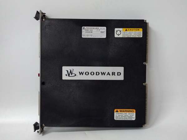
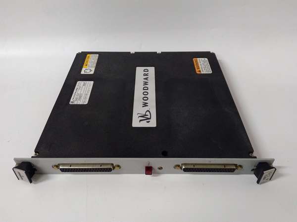
WOODWARD 5466-031
The Real-World Problem It Solves
Trying to control a high-pressure fuel valve or a steam turbine guide vane directly from a CPU’s weak analog output is a recipe for disaster. You’ll fight hysteresis, signal noise, and sluggish response times. The 5501-432 acts as a dedicated, high-current muscle amp that sits right on the MicroNet backplane. It takes the digital command from the CPU and physically drives the actuator with precision, handling all the noisy analog feedback loops locally so the main processor doesn’t choke.
Where you’ll typically find it:
- In the heart of a MicroNet rack controlling the liquid fuel bypass valve and the gas fuel control valve on a GE Frame turbine.
- Managing the inlet guide vanes (IGVs) of a compressor station to optimize surge control.
- Handling dual-fuel valve positioning in power generation facilities where split-second accuracy prevents flameouts or overspeed trips.
It offloads the heavy lifting of analog control from your main CPU and gives your mechanical valves the crisp, responsive control they desperately need.
Hardware Architecture & Under-the-Hood Logic
This module is essentially two independent, high-performance analog output and feedback conditioning loops packed into a single slot. It talks to the CPU across the backplane but executes the dirty work of analog control autonomously.
- Command Reception: The module receives a digital setpoint command from the MicroNet CPU via the backplane bus.
- Signal Processing & Output Drive: An internal DSP processes the command and generates a precise output current (0-200mA) capable of driving industrial servos or I/P converters directly without external amplifiers.
- Feedback Acquisition: Simultaneously, it excites and reads up to two LVDTs/RVDTs per channel. It demodulates the AC feedback signals, converts them to digital position values, and compares them against the commanded position.
- Closed-Loop Correction: The module continuously adjusts the 200mA output current to minimize the error between the commanded position and the actual LVDT feedback, ensuring the valve hits the exact mechanical stop the CPU asked for.

WOODWARD 5466-031
Field Service Pitfalls: What Rookies Get Wrong
Skipping the “Null” Calibration on LVDTs
Rookies assume that because it’s a smart digital module, it will automatically figure out the LVDT’s electrical center. They bolt the LVDT to the valve, power up, and watch the valve slam to one extreme limit because the module thinks 50% stroke is actually at 0%.
- Field Rule: Never skip the mechanical and electrical zeroing of the LVDT/actuator assembly before handing control over to the 5501-432. Perform a full mechanical stroke test: command 0%, check physical position and feedback readback; command 100%, check again. Adjust the LVDT core position mechanically until the feedback matches the physical travel perfectly across the entire range.
Overlooking Backplane Power Budgeting
The 5501-432 drives real-world inductive loads (solenoids, voice coils, or I/P transducers) which draw significant current. Rookies stuff a MicroNet rack full of these actuator modules, power it up, and the entire rack resets intermittently because the cumulative current draw during actuator movement exceeds the backplane’s +5VDC supply rating.
- Quick Fix: Do the math before you install. Calculate the worst-case simultaneous current draw of all actuator modules in the rack. If you are pushing the limits of the backplane power supply (typically sourced from the CPU or a dedicated rack power module), redistribute the modules or upgrade the rack’s power supply. Monitor the 5V bus with a scope during heavy actuator movement; if it dips below 4.75V, you have a power integrity issue.
Floating Grounds on Analog Feedback
When an actuator binds up or oscillates wildly, rookiеs blame the 5501-432 or the LVDT. Often, the real culprit is a broken shield or a ground loop in the feedback wiring. Noise from nearby VFDs or contactor coils couples into the LVDT signal wires, tricking the module’s ADC into thinking the valve is hunting.
- Field Rule: Keep your LVDT/RVDT signal cables away from high-current AC wiring. Ensure the shield is tied to a solid earth ground at the actuator junction box and left floating at the 5501-432 end to prevent ground loops. If you have to question the grounding, grab a multimeter and verify continuity from the LVDT casing to the module’s analog ground terminal—it should be rock solid.
Commercial Availability & Pricing Note
Please note: The listed price is for reference only and is not binding. Final pricing and terms are subject to negotiation based on current market conditions and availability.


