

Description
Hard Numbers: Technical Specifications
- I/O Configuration: 48 Discrete Inputs, 24 Discrete Outputs
- Input Voltage: 18–32 VDC (24 VDC Nominal)
- Power Consumption: 6.5 W @ 24 VDC
- Output Current: 2 A per output channel (typical solid-state or relay drive)
- Isolation: Optical isolation on discrete inputs to prevent external signal interference
- Communication: MicroNet proprietary backplane bus
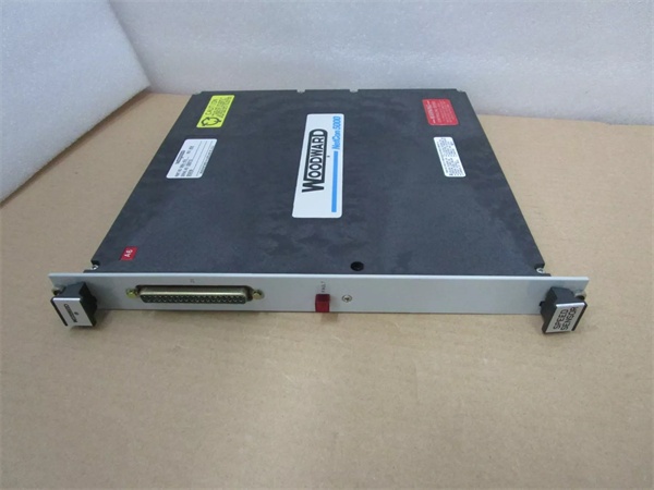
- Connector Type: Two high-density connectors interfacing to Functional Terminal Modules (FTMs)
- Indicators: 1 Red Fault LED on the front panel
- Environmental Rating:
- Operating Temp: 0°C to +55°C (some sources state extended range -40°C to +85°C depending on configuration)
- Storage Temp: -40°C to +40°C (or up to +85°C per extended specs)
- Certifications: UL, ATEX, CE (EMC), DNV, ABS, LRS
- Dimensions: Approx. 12.5″ × 12.5″ × 5″ (317 mm × 317 mm × 127 mm)
- Weight: Approx. 2.5–3.0 kg (5.5–6.6 lbs)
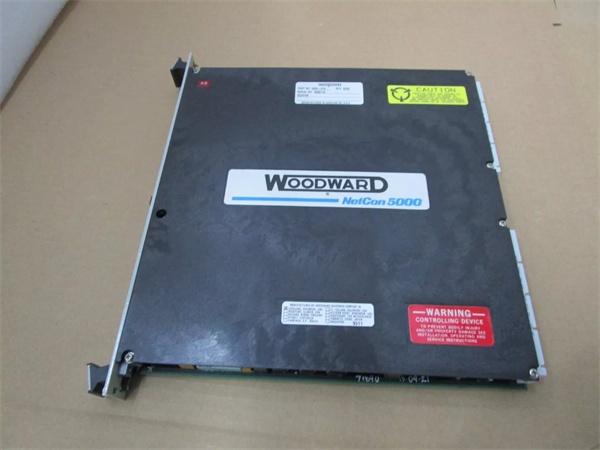
WOODWARD 5464-648
The Real-World Problem It Solves
In complex power generation or oil & gas compression facilities, control panels can quickly become a tangled web of wires, sensors, and actuators. Managing dozens of individual on/off signals—such as emergency stop buttons, limit switches, solenoid valves, and alarm horns—using multiple low-density modules eats up valuable rack space and complicates wiring.
The Woodward 5466-258 collapses this complexity into a single, high-density module. It acts as a massive, highly organized digital switchboard, capable of monitoring 48 separate field devices and driving 24 outputs simultaneously. By offloading this high volume of digital I/O from the main CPU and localizing it to a single backplane-compatible card, it drastically reduces cabinet footprint, simplifies system architecture, and ensures that critical on/off commands are processed with zero latency.
Where you’ll typically find it:
- In the local control cabinets of gas and steam turbines, monitoring critical trip conditions (e.g., overspeed, over-temperature) and driving shutdown solenoids.
- Integrated into Vertex-Pro compressor control panels, managing start/stop sequences, anti-surge valve staging, and status indication to the plant DCS.
- In power generation switchgear, handling circuit breaker status, fault relays, and synchronization signals.
Hardware Architecture & Under-the-Hood Logic
Unlike passive terminal blocks that merely pass wires through, the 5466-258 is an active signal-processing powerhouse designed for deterministic control.
- Optical Isolation Barriers: The 48 discrete inputs are protected by robust optical isolators. This creates a galvanic barrier between the noisy, high-voltage field wiring and the sensitive 5V/3.3V logic of the MicroNet backplane. It ensures that a voltage spike from a nearby VFD starting up won’t corrupt the digital signal or damage the controller.
- High-Current Output Drivers: The 24 outputs are driven by high-current solid-state relays or transistor arrays capable of sinking or sourcing 2A each. This allows the module to directly drive heavy-duty industrial components like pilot lights, alarm bells, and small solenoid valves without needing external interposing relays.
- Glitch-Free Scanning: The onboard microcontroller continuously scans all 48 inputs in hardware-level microseconds. It debounces mechanical switch contacts internally and pushes a clean, deterministic snapshot of the system’s digital state to the main CPU via the backplane, ensuring the control logic never acts on a phantom noise spike.

WOODWARD 5464-648
Field Service Pitfalls: What Rookies Get Wrong
The “Phantom Trip” from Mechanical Switch Bounce
Rookies often connect a mechanical emergency stop button or a limit switch directly to a 5466-258 input and assume the MicroNet controller will read it perfectly. However, mechanical contacts “bounce” (rapidly open and close) for a few milliseconds when pressed. The 5466-258 is fast enough to read this bouncing as multiple rapid on/off cycles, which can cause the control logic to chatter or falsely trigger a trip.
- Field Rule: Always program a 50-100ms debounce timer in the MicroNet GAP (Graphical Application Programmer) software for any input connected to a mechanical contact. This tells the CPU to ignore rapid fluctuations and only register the signal if it stays stable for the set duration.
Overloading Outputs with Inductive Kickback
When driving a 24VDC solenoid valve or a relay coil, rookiеs often forget that when the magnetic field collapses, it generates a massive voltage spike (inductive kickback) that can arc across the module’s output transistors. Doing this repeatedly will permanently weld the module’s output transistor in the “ON” position.
- Quick Fix: Always install a flyback diode (for DC coils) or a snubber circuit (RC network) across the terminals of any inductive load connected to the 5466-258 outputs. This gives the inductive spike a safe path to dissipate, protecting the delicate silicon inside the Woodward module.
Creating Ground Loops with Sinking vs. Sourcing Confusion
The 5466-258 can be wired for sinking (current flows into the module) or sourcing (current flows out of the module) configurations. Rookies often mix them—connecting a sourcing sensor to an input expecting a sinking signal, or vice-versa. This doesn’t just result in no signal; it can create a low-impedance path to ground, causing the 24VDC power supply to struggle, leading to voltage drops that reset other modules in the rack.
- Field Rule: Before energizing a newly wired 5466-258, use a multimeter to verify the polarity and voltage level of every field device connected to the inputs and outputs. Ensure your 0V (DC Common) reference is consistently distributed across the entire rack to prevent ground loops.
Commercial Availability & Pricing Note
Please note: The listed price is for reference only and is not binding. Final pricing and terms are subject to negotiation based on current market conditions and availability.


