
Description
Hard-Numbers: Technical Specifications
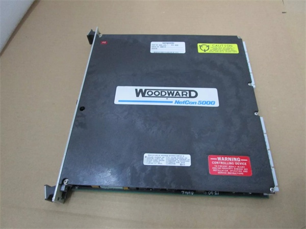
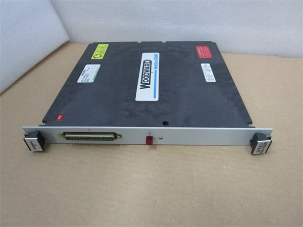
- Part Number: 5464-334
- Input Type: 8 Channels, Isolated 4-20mA Analog
- Power Supply: 24 VDC (Operational Range: 10 – 60 VDC)
- Maximum Operating Current: 12 VDC
- Isolation Protection: 3000 VDC
- Communication Interface: VME bus / Proprietary Backplane
- Operating Temperature: -25°C to +70°C
- Mounting: DIN Rail / Card Guide Mounting
- Indicators: Onboard LED (Power/Status/Fault)
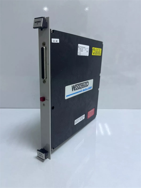
5464-334
The Real-World Problem It Solves
In a turbine skid or refinery compressor station, ground loops and electrical noise from large VFDs or lightning strikes can fry sensitive control system inputs, leading to spurious trips and unplanned downtime. The 5464-334 acts as a rugged barrier, optically isolating each of its 8 analog input channels to ensure that a fault on one field loop doesn’t cascade and take down the entire control rack.
Where you’ll typically find it:
- Installed in the local control panel of a GE Frame 5 or similar industrial gas turbine, interfacing pressure transmitters and temperature sensors to the main MicroNet processor.
- Mounted on the DIN rail of a wood-fired power plant’s fuel feed control system, conditioning the 4-20mA signals from the drag chain load cells.
- Retrofitted into older 5400-series cabinets to replace failed analog input cards, restoring critical speed and exhaust temperature readings to the governor.
It keeps noisy field wiring from crashing your control logic.
Hardware Architecture & Under-the-Hood Logic
This module is essentially a high-density signal conditioning and digitization front-end. It bridges the gap between real-world analog sensors and the digital world of the turbine’s main processor.
- Signal Conditioning: Each of the 8 channels receives a 4-20mA current loop from a field transmitter (e.g., pressure, position, or temperature).
- Optical Isolation: Before the signal reaches the A/D converter, it passes through opto-isolators. This provides 3000VDC of galvanic isolation, breaking any potential ground loops between the field devices and the control system chassis.
- A/D Conversion: An onboard microcontroller manages the analog-to-digital conversion for all channels, executing automatic calibration routines using an internal precision voltage reference.
- Data Transmission: The digitized, noise-free data is packaged and transmitted to the main CPU via the backplane (VME-based) using a broadcast key system, minimizing the host processor’s workload.
Field Service Pitfalls: What Rookies Get Wrong
Blown Input Channels from Inductive Kickback
Junior techs often forget that 4-20mA loops powering solenoid valves or long cable runs act like inductors. When the power is interrupted, the collapsing magnetic field generates a high-voltage spike that will instantly blow the fragile input conditioning circuitry on the 5464-334.
- Field Rule: Always install flyback diodes across any inductive loads in the loop. If the loop includes long runs in conduit near high-voltage cables, add a 24VDC surge suppressor across the positive and negative terminals at the module end.
False Alarms Due to “Ghost Voltages” on Open Circuits
A common mistake during commissioning is leaving a spare analog input channel unterminated. Because the inputs are high-impedance, they will pick up ambient electrical noise from the cabinet, causing the processor to read erratic, fluctuating values that can trigger false alarms or bump the turbine into a lower control mode.
- Field Rule: Never leave inputs floating. If a channel is not used, land a 250-ohm resistor across the terminals to pull the input to 0mA, or explicitly disable/unused the channel in the application program’s I/O mapping table.
Using Undersized Wire Gauge for Long Cable Runs
In large plants, running 24 AWG instrument cable for 4-20mA loops over 1000 feet leads to significant voltage drop. The 5464-334 might only see 12VDC at the terminal instead of the required 24VDC, causing the module to cycle between “OK” and “Undervoltage Fault.”
- Field Rule: Do the voltage drop math before pulling wire. For runs over 500 feet, step up to 18 AWG or 16 AWG conductors. Always measure the loop voltage at the deviceunder load, not just at the power supply.
5464-334
Commercial Availability & Pricing Note
Please note: The listed price is for reference only and is not binding. Final pricing and terms are subject to negotiation based on current market conditions and availability.


