
Description
Hard-Numbers: Technical Specifications
Note: Public datasheets for the 47373-02M are largely obsolete. The following specifications represent typical values for this class of Woodward actuator. Verify against the physical unit’s nameplate before applying power.
- Part Number: 47373-02M
- Supply Voltage: 12 VDC or 24 VDC (Verify coil rating on nameplate)
- Current Draw: ~3.5 A to 5.0 A (Holding current at nominal voltage)
- Stroke Length / Rotation: Typically 1.0 to 1.5 inches (25-38 mm) or 75 degrees of rotation
- Force / Torque Output: 15 to 35 lb-in (depending on lever arm mechanical advantage)
- Operating Temperature: –40°C to +70°C (–40°F to 158°F)
- Enclosure Rating: IP54 (Dust and splash resistant)
- Electrical Connections: Screw terminals or DT-series sealed connectors
- Mounting: Flange mount with metric threaded adjustment slots
Woodward 47371-01
The Real-World Problem It Solves
Finding a direct-replacement actuator for a 20-year-old generator set or marine propulsion engine is a nightmare. Standardizing on a 47373-02M allows you to ditch clunky, leaking hydraulic preamplifiers or worn-out mechanical linkages and bring the engine under precise electronic control.
Where you’ll typically find it:
- Retrofitted onto the side of a Woodward PG-PL or PSG governors on aging generator sets.
- Coupled directly to the fuel rack of a large-bore stationary diesel engine in a pumping station.
- Serving as the primary positioning device in legacy compressor skids requiring upgraded speed control.
This actuator takes a standard 4-20mA control signal and converts it into repeatable mechanical movement, eliminating the deadband and hysteresis common in older hydraulic systems.
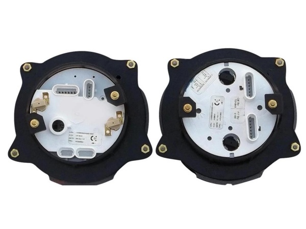
Hardware Architecture & Under-the-Hood Logic
The 47373-02M is a brute-force electromechanical device designed to survive extreme vibration and temperature swings in engine rooms. It relies on a simple, robust design to deliver consistent thrust or torque to heavy mechanical linkages.
- Solenoid / Motor Coil: Receives the variable current or PWM signal from the governor drive or PLC. The magnetic field strength changes linearly with the input demand.
- Drive Train (Shaft/Linkage): The magnetic field drives an internal plunger or armature, which is mechanically linked to the external actuator shaft or lever arm.
- Internal Spring Return: A heavy-duty spring provides the fail-safe mechanism. In the event of a power loss or loss of signal, the spring forces the actuator to its predetermined safe position (usually fuel-off or no-load) to prevent an overspeed or runaway condition.
Woodward 47371-01
Field Service Pitfalls: What Rookies Get Wrong
Assuming the “M” is Just a Revision
A rookie orders a 47373-02 to replace a failed 47373-02M. He forces the mounting bolts in, gets the actuator slightly cocked, and within a week, the internal bearings seize due to lateral side-loading.
- Field Rule: The “M” suffix almost invariably denotes Metric threading or hole spacing. Never try to drill out a panel or force imperial bolts into metric holes. Fabricate a proper adapter plate if you must cross from metric to imperial, ensuring the actuator sits perfectly square to the linkage.
Ignoring the Nameplate Voltage
Working on a mixed 12V/24V site, a rookie assumes the 47373-02M is 24V because the rest of the panel is. He applies 24V, the actuator slams to full throttle, and the coil immediately starts smoking.
- Field Rule: Always, always check the physical nameplate on the actuator body before wiring. If the original tag is missing, use a multimeter to check the coil resistance and compare it to Woodward’s standard resistance tables for their 12V vs. 24V coils. When in doubt, trace the original wiring back to the power supply.
Commercial Availability & Pricing Note
Please note: The listed price is for reference only and is not binding. Final pricing and terms are subject to negotiation based on current market conditions and availability.


