
Description
Hard-Numbers: Technical Specifications
- Part Number: 47371-01M
- Supply Voltage: 12 VDC or 24 VDC (must verify specific coil rating)
- Current Draw: 3.5 A holding current at 18 VDC
- Stroke Length: 1.0 to 1.5 inches (25-38 mm)
- Force Output: 15 to 35 lb-in (dependent on lever arm ratio)
- Operating Temperature: –40°C to +70°C (–40°F to 158°F)
- Enclosure Rating: IP54 (dust and splash resistant)
- Electrical Connections: Screw terminals or Deutsch DT series connectors
- Mounting: Flange mount with metric slotted holes for fine adjustment
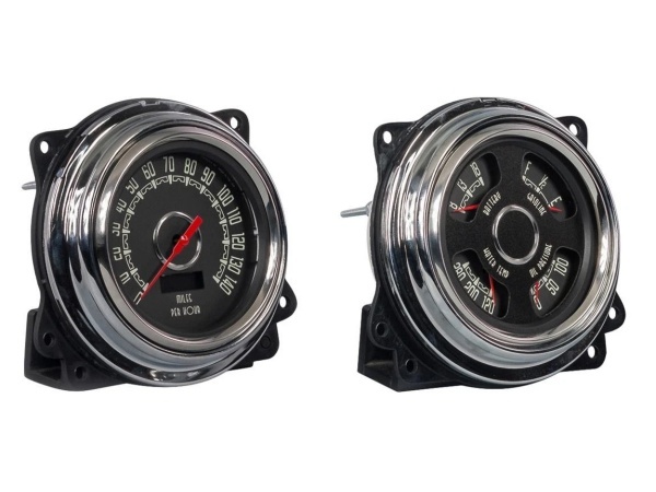
Woodward 47371-01
The Real-World Problem It Solves
Mechanical and hydraulic governors wear out. Linkages get sloppy, and response times lag, causing frequency drift on generator sets or poor fuel economy on compressors. Swapping in a 47371-01M brings solid-state reliability to an old prime mover without replacing the entire governor assembly. The “M” designation ensures proper fitment with metric-threaded hardware commonly found on European or Asian engine packages.
Where you’ll typically find it:
- Bolted onto the side of a Woodward PG-PL governor during an electronic retrofit.
- Directly coupled to the fuel rack of a large stationary diesel engine.
- Serving as the primary positioning device in a legacy gas turbine fuel control skid.
This actuator takes a standard 4-20mA control signal and converts it into precise, repeatable mechanical movement, eliminating the hysteresis common in older equipment.
Hardware Architecture & Under-the-Hood Logic
The 47371-01M is built like a tank because it has to survive the vibration and thermal shock of an engine room. It relies on a simple, proven design to push and pull heavy mechanical linkages without burning out.
- Solenoid/Coil Assembly: Receives the variable current signal from the governor or PLC. The magnetic field strength changes linearly with the input current.
- Linear Drive Shaft: The magnetic field moves an internal plunger or armature. This motion is translated directly to the external linkage arm.
- Internal Spring Return: A heavy-duty spring provides the fail-safe mechanism. If power is lost, the spring forces the actuator to its default position (usually fuel-off or no-load) to prevent a runaway condition.
Field Service Pitfalls: What Rookies Get Wrong
The “Hot” Coil Burnout
A rookie wires the actuator to a continuous 24VDC supply instead of a pulsed or current-controlled output. The coil overheats within minutes, melting the insulation and seizing the plunger.
- Field Rule: Never apply full system voltage directly to the actuator coil unless specifically stated in the datasheet. Use a PWM driver or a current-limiting resistor network as recommended by Woodward for your specific application.
Linkage Binding and Premature Wear
The actuator is mounted slightly off-axis from the fuel rack. As it cycles, the lateral force binds the shaft, causing the engine to hunt for the right speed.
- Field Rule: Use a flexible ball-joint linkage. Rigid connections will transfer vibration back into the actuator, destroying the internal bearings. Ensure the actuator shaft travels perfectly parallel to the fuel rack movement.
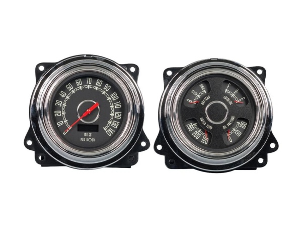
Woodward 47371-01
Commercial Availability & Pricing Note
Please note: The listed price is for reference only and is not binding. Final pricing and terms are subject to negotiation based on current market conditions and availability.


