
Description
Key Technical Specifications
-
Model Number: 1887-031
-
Manufacturer: Woodward Inc.
-
Platform: NetSim Network Simulation System
-
Processor: Embedded ARM Cortex-A53 quad-core, 1.2 GHz
-
Memory: 2GB DDR4 RAM, 8GB eMMC storage for configurations/logs
-
Ethernet Ports: 4 total—Port A/B (copper 10/100/1000 Base-T), Port C/D (SFP 100/1000 Base-X)
-
Latency Injection: 0-10,000 ms in 0.1 ms increments, asymmetric (independent A→B and B→A)
-
Jitter: Gaussian distribution, 0-100% of base latency, configurable standard deviation
-
Packet Loss Models: Random (Bernoulli), Burst (Gilbert-Elliott), Periodic (time-based), Bit error injection
-
Bandwidth Throttling: 1 Kbps to 1 Gbps per port pair, granular control
-
Packet Reordering: Configurable out-of-order delivery simulation
-
Duplication: 0-50% packet duplication rate
-
Corruption: Bit-level error injection at specified probability
-
Filtering: Layer 2 MAC, Layer 3 IP, Layer 4 port-based traffic selection
-
Management Interface: Web UI (HTTP/HTTPS), SSH CLI, SNMP v2c/v3
-
Power: 12VDC external adapter, 15W typical consumption
-
Mounting: Benchtop or DIN rail (optional kit)
-
Certifications: CE Marked, FCC Class A, industrial emissions compliant

WOODWARD 9907-167
Field Application & Problem Solved
In the field, the 1887-031 solves a problem most engineers don’t know they have until it’s too late: their control system was tested on a pristine lab network, but the plant network is a disaster of VLAN misconfigurations, overloaded switches, and 300-foot cable runs through electrically noisy cable trays. I’ve commissioned systems that worked flawlessly in the factory FAT, then failed intermittently in the field because no one tested what happens when the network has 50ms jitter or 0.1% packet loss. This module exists to inject that reality into your testing phase.
You’ll find this box on the bench of any serious controls integrator or in the test lab of plants running distributed turbine control systems. It’s not a field-installed device—it’s a validation tool. When Woodward ships a new 505E with Ethernet Modbus TCP, or when you’re integrating a ProTech-GII into a plant-wide DCS network, you need to know the controller won’t hang, fault, or trip the turbine when the network degrades. The 1887-031 sits between your controller and your HMI/SCADA system, deliberately degrading the connection to find the breaking point.
The core value is finding failure modes before they find you. Controllers handle network timeouts differently—some retry forever, some fault immediately, some buffer data until memory overflows. The 1887-031 lets you characterize that behavior. I worked a job where the turbine would mysteriously trip every Tuesday at 2 AM. Turned out the plant’s backup software ran then, saturating the network with traffic bursts. The controller’s Modbus TCP timeout was set to 500ms; under load, responses took 600ms. The controller flagged communication loss and initiated a protective trip. We reproduced that exact scenario in the lab with this module, proved the fix (increasing timeout to 2 seconds), and deployed with confidence.
Where this distinguishes itself from generic network tools like WANem or hardware from Ixia/Spirent: it’s purpose-built for industrial control timing. Generic network emulators think in terms of web browsing and file transfers—latency matters, but millisecond precision doesn’t. The 1887-031 operates at the microsecond level for timestamping and injection. It understands deterministic industrial protocols. It can filter and impair only your Modbus TCP traffic while leaving SNMP management traffic untouched. That’s critical when you’re testing whether the controller can still receive a trip command from the safety system while its HMI data is delayed.
Installation & Maintenance Pitfalls (Expert Tips)
Asymmetric Latency: The Forgotten Direction
Most engineers test latency as a round-trip number—”I’ll add 100ms delay.” But control networks are asymmetric. Your controller sends a 64-byte Modbus poll; the HMI responds with a 1500-byte block of data. The large packet takes longer to serialize, longer to route through congested switches. The 1887-031 lets you set independent delays for A→B and B→A. I’ve seen systems that tolerate 200ms A→B latency (controller to HMI) but trip on 50ms B→A because the controller’s watchdog timer expects responses faster than the impaired return path allows. Always characterize both directions separately. Set A→B to your expected field latency, then sweep B→A from 0ms upward until you find the controller’s timeout threshold. Document that number—it’s your safety margin.
Burst Loss vs. Random Loss: Different Failure Modes
The module offers multiple packet loss models. Random loss (Bernoulli) drops packets independently—1% loss means 1 in 100 packets disappears. Burst loss (Gilbert-Elliott) models real network failures: a switch buffer overflows, and you lose 50 consecutive packets before recovering. Industrial controllers handle these differently. Random loss at 1% might cause slow data updates but no fault. Burst loss of 50 packets almost always triggers a communication fault alarm—even at 0% average loss if the burst duration exceeds the controller’s missing message tolerance. Test both. Real plant networks have burst characteristics during switchover events, not random noise.
Bandwidth Limiting: The Serialization Delay Trap
When you throttle bandwidth to 1 Mbps to simulate a congested WAN link, remember serialization delay. A 1500-byte Ethernet frame takes 12 microseconds at 1 Gbps, but 12 milliseconds at 1 Mbps. That’s three orders of magnitude. If your controller sends large blocks of historical data, that serialization delay adds to your configured latency. I’ve seen engineers configure 100ms latency plus 1 Mbps bandwidth limit, then wonder why actual delay measures 250ms. Do the math: 1500 bytes × 8 bits/byte ÷ 1,000,000 bits/second = 12ms per frame. Ten frames in a burst = 120ms serialization + 100ms configured = 220ms total. The 1887-031 shows you this in the statistics page—use it.
SFP Compatibility: The Third-Party Trap
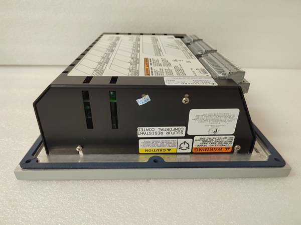
Ports C and D take SFP modules for fiber connectivity. The manual lists “compatible with standard 1000Base-SX/LX SFPs.” That’s partially true. I’ve installed third-party SFPs that linked up fine at 1 Gbps but failed to negotiate at 100 Mbps when the 1887-031 was configured for slower speeds to match an older controller. The module’s PHY chip has specific timing requirements for auto-negotiation. Use Woodward-approved SFPs (part numbers 5437-1047 for multimode, 5437-1048 for singlemode) or verify your third-party module supports Clause 37 auto-negotiation. Otherwise, you’ll spend hours troubleshooting “cable faults” that are actually PHY mismatches.
Configuration Persistence: The Power Cycle Surprise
The 1887-031 stores configurations in flash memory, but there’s a catch: active impairments are volatile. If you set up 50ms latency and 1% loss for a test, then power cycle the module, it boots with impairments disabled (pass-through mode). This is a safety feature—if the box fails in a production environment, you want it to become a wire, not a brick. But during long-term testing, if you lose power and don’t notice, you’re running unimpaired traffic thinking you’re still testing degraded conditions. Always verify the “Impairments Active” LED after any power event. Better yet, save your config as a profile and set it to auto-load on boot if your test procedure allows.
Timestamping Accuracy: The NTP Dependency
The module timestamps packets for latency measurement using its internal clock. For absolute accuracy across multiple NetSim units (testing redundant network paths), you need synchronized time. The 1887-031 supports NTP client mode, but it doesn’t enforce it. I’ve seen test results where Path A showed 45ms latency and Path B showed 52ms, but the 7ms difference was actually clock drift between two unsynchronized NetSim boxes, not real network asymmetry. Always enable NTP, point to the same stratum-1 source, and verify synchronization status before collecting data. For critical validation, use PTP (IEEE 1588) if your infrastructure supports it—the 1887-031 has hardware PTP timestamping on the -002 revision.
WOODWARD 9907-167
Technical Deep Dive & Overview
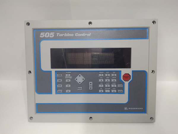
The 1887-031 is a specialized network emulator designed specifically for testing industrial control system behavior under non-ideal network conditions. Unlike IT-focused network tools that prioritize throughput and protocol conformance, this module focuses on timing precision and deterministic impairment—critical for control systems where a 100ms communication delay can trigger a protective shutdown.
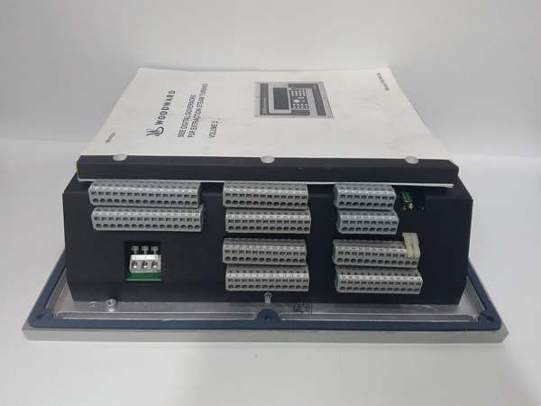
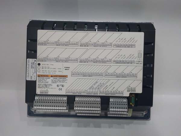
Physically, the device is a compact box roughly the size of a paperback book. The front panel presents four Ethernet ports in two pairs: A/B for copper connections to standard controllers and HMIs, C/D for fiber SFP connections when testing across simulated long-distance links. Each port pair operates as a transparent bridge—traffic enters port A, passes through the impairment engine, exits port B. The module is protocol-agnostic at Layer 2; it doesn’t care if you’re running Modbus TCP, EtherNet/IP, OPC UA, or proprietary Woodward protocols. It sees Ethernet frames and applies impairments based on configurable filters.
The impairment engine runs on a quad-core ARM processor with dedicated network interface controllers (NICs) featuring hardware timestamping. When a frame arrives at port A, the NIC records the arrival time with microsecond precision. The frame passes to the impairment logic, which may buffer it (latency), drop it (loss), duplicate it, reorder it, or corrupt specific bits. The modified frame then queues for departure at port B, with another hardware timestamp marking transmission. The difference between arrival and departure timestamps, minus processing overhead, equals the injected latency.
Latency injection uses a token-bucket algorithm with high-resolution timers. You configure a base latency (e.g., 50ms) and optional jitter (e.g., ±10ms Gaussian distribution). The module maintains separate queues for each traffic class (based on VLAN priority or DSCP bits), allowing you to impair critical control traffic differently than background HMI updates. This matters when testing Quality of Service (QoS) configurations—verify that your controller’s emergency trip command (high priority) gets through even when historical data logging (low priority) is delayed by congestion.
Packet loss modeling goes beyond simple random dropping. The Gilbert-Elliott model simulates burst errors common in industrial environments: a switch port flaps, a cable is jostled, a wireless link fades. The model defines two states—”good” (low loss probability) and “bad” (high loss probability)—with transition probabilities between them. This creates realistic loss patterns: long periods of stability interrupted by brief outages. Controllers often survive steady 1% random loss but fail when 100% loss occurs for even 500ms—their state machines assume communication is restored after a few retries, not realizing the network is completely down.
Bandwidth throttling implements a traffic shaper with configurable bucket depth. This simulates constrained links—T1 lines, overloaded switches, or radio modems. The shaper enforces average bit rate while allowing configurable burst tolerance. For control systems, this reveals how controllers handle backpressure. Some protocols (Modbus TCP) have no flow control; the sender transmits regardless of receiver capacity. Under bandwidth constraint, packets buffer until the module’s queue overflows, then drop. Does the controller detect the dropped packets and throttle its poll rate, or does it continue flooding the network with retransmissions? The 1887-031 lets you observe and characterize this behavior.
The management interface provides both web UI and SSH CLI access. The web interface displays real-time statistics: packets in/out, current latency, loss rate, queue depths. It allows quick configuration of common impairment profiles—”T1 Line” (1.5 Mbps, 50ms latency), “Congested Plant Network” (10 Mbps, 5% loss, 100ms jitter), “Satellite Link” (512 Kbps, 500ms latency, high jitter). For detailed testing, the CLI offers precise control: set latency 47.5, set loss random 0.25, set jitter gaussian 10.0. Configuration scripts can be saved and loaded, enabling repeatable test procedures.
Integration with Woodward controllers is straightforward but requires attention to topology. The 1887-031 is inserted inline between the controller’s Ethernet port and the plant network. For redundant network testing (common with 505E dual-Ethernet configurations), two modules may be used—one in each path—with synchronized impairment profiles to test failover behavior. When the primary path’s latency exceeds the controller’s failover threshold, does the switch to the secondary path occur cleanly? Does the controller maintain output stability during the transition? These are questions you answer in the lab, not the field.
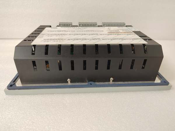
Power is provided by an external 12VDC adapter. The module consumes minimal power (15W typical) and generates little heat, suitable for continuous operation in test benches. There are no moving parts—solid-state storage, passive cooling on the processor. The SFP cages accept standard small form-factor pluggable modules; the module detects insertion and reports optical power levels in the diagnostic page, useful for verifying fiber link budgets.


