

Description
Hard-Numbers: Technical Specifications
- Rated Voltage: 12 VDC
- Coil Configuration: Dual Coil (Pull + Hold) wired in parallel
- Pull Current: 28 A (momentary inrush at 12VDC)
- Hold Current: 1.67 A (continuous duty at 12VDC)
- Pull Force: 19 lbs (85 N) minimum at 12VDC
- Hold Force: 38 lbs (169 N) minimum at 12VDC
- Linear Stroke: 2.0 inches (50.8 mm)
- Duty Cycle: Intermittent (Pull) / Continuous (Hold)
- Operating Temperature: -40°C to +85°C
- Electrical Connection: 12-inch flying leads (Tinned wire)

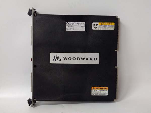
Woodward 5466-1045
The Real-World Problem It Solves
When you have a massive generator engine, a tiny single-coil solenoid isn’t going to cut it. It simply doesn’t have the mechanical throw or the magnetic grit to overcome the stiff return springs on a large fuel rack. The 1751-12E2U2B1A delivers a full 2 inches of linear travel with nearly 40 pounds of holding force, ensuring your fuel system snaps to “run” and stays there, even under heavy vibration.
Where you’ll typically find it:
- Mounted on the fuel injection pump of large industrial diesel generators (often Cummins or Detroit Diesel).
- Controlling the main fuel shutoff linkage on marine propulsion engines or frac pumps.
Bottom line: It’s a high-torque, long-stroke workhorse designed to muscle heavy fuel racks into the “run” position and hold them there reliably.
Hardware Architecture & Under-the-Hood Logic
This is a classically engineered, dual-coil proportional actuator built for pure mechanical leverage. Its internal design balances the need for high starting torque with long-term thermal stability.
- The Initial Pull: When 12VDC is applied, both the low-resistance pull coil and the high-resistance hold coil are energized simultaneously. This dumps a massive ~28A surge into the coil pack, generating an intense magnetic field.
- Rapid Stroke: This magnetic field violently pulls the hardened steel plunger upward, overcoming the resistance of the fuel rack return spring and any static friction in the linkage.
- Seated Hold: Once the plunger reaches the fully seated position (2 inches of travel), the inductive load stabilizes. The hold coil dominates the circuit, dropping the current draw down to a safe 1.67A continuous.
- Mechanical Lock: The plunger is fitted with a 1/4-20 UNC clevis pin, which attaches directly to the engine’s fuel control arm. As the plunger pulls up, it physically rotates the fuel arm into the “open” or “run” position.
- Fail-Safe Dropout: The moment the 12V signal is lost, the magnetic field collapses instantly. The heavy-duty internal spring forcefully ejects the plunger downward, driving the fuel rack to the “zero fuel” shutdown position.
Woodward 5466-1045
Field Service Pitfalls: What Rookies Get Wrong
Undersized Power Supply and Relay Chatter
That 28-amp inrush current will weld the contacts of a standard 10-amp automotive relay shut in a matter of days. Rookies often use whatever relay is lying around in the parts bin, leading to intermittent starting issues.
Field Rule: You must use a heavy-duty 40-amp relay (preferably a sealed automotive starter solenoid) to switch the 12VDC feed. Run a dedicated 10AWG or 12AWG fused line directly from the battery busbar to handle the initial current spike without significant voltage drop.
Clevis Pin Binding and Side-Load
The 1751 series has a long 2-inch stroke. If the clevis pin is not perfectly aligned with the fuel lever, the plunger will scrape against the coil housing. This creates massive friction, generating heat and eventually causing the plunger to seize in the “run” position—a catastrophic failure on an overspeed trip.
Quick Fix: Loosen the clevis jam nut and ensure the pin has at least 1/16th of an inch of horizontal play. Manually cycle the fuel lever through its full range of motion (by hand) to confirm the solenoid plunger moves smoothly without binding.
Heat Soak and Insulation Breakdown
Mounting this actuator onto a hot engine block without proper isolation will cook the internal coil insulation. The black epoxy (E-coating) helps, but it’s not a miracle worker against radiant exhaust heat.
Field Rule: If the mounting surface exceeds 185°F (85°C), install a simple aluminum heat shield between the actuator flange and the engine block. Always use a star washer on the mounting bolt to bite through any paint or corrosion, ensuring a rock-solid electrical ground.
Commercial Availability & Pricing Note
Please note: The listed price is for reference only and is not binding. Final pricing and terms are subject to negotiation based on current market conditions and availability.


