
Description
Product Core Brief
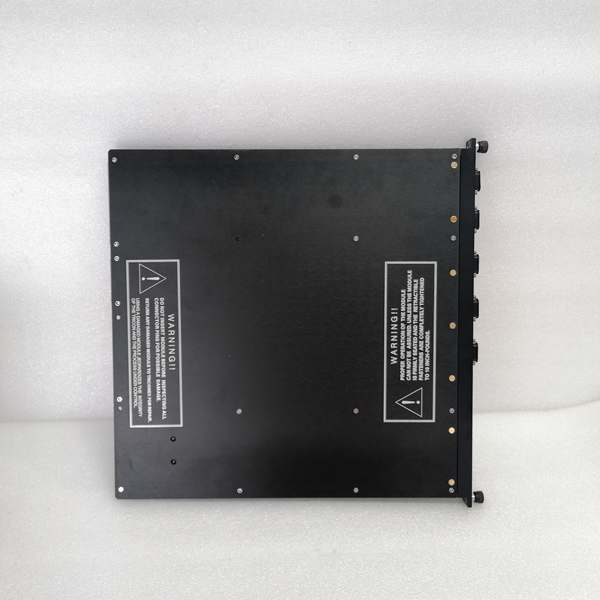
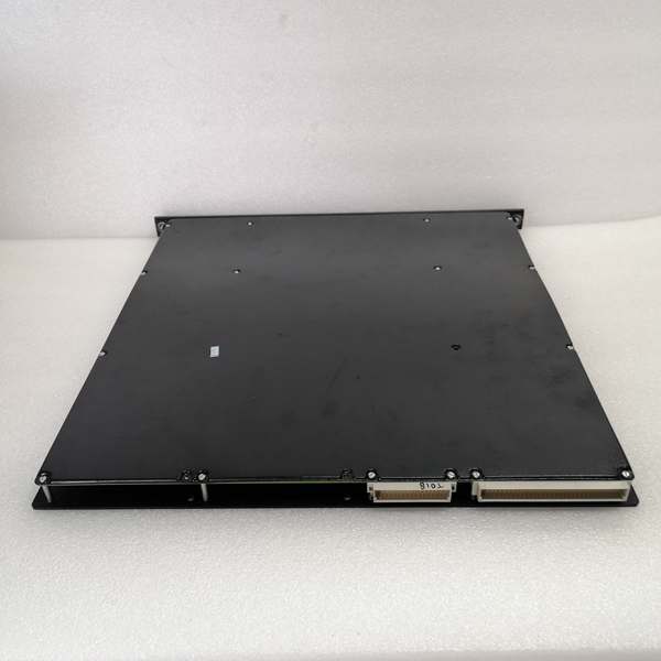
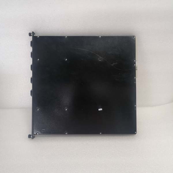
- Model: 4351B
- Brand: TRICONEX
- Series: Tricon TMR Safety System
- Core Function: Facilitates data exchange and programming across safety systems and external devices.
- Product Type: Communication Interface Module
- Key Specs: Dual Ethernet | 4 Serial Ports | SIL3 TMR | Hot-Swap Supported
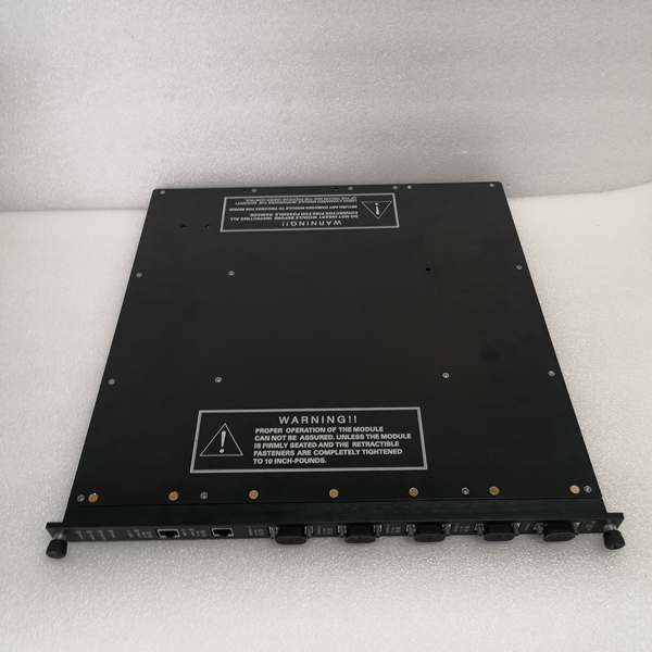
TRICONEX 4351B
Key Technical Specifications
- Architecture: Triple Modular Redundancy, 2oo3 voting logic
- Ethernet Ports: 2 x RJ45, 10/100 Mbps auto-negotiation
- Serial Ports: 4 x DB9, RS-232/RS-485, max 115.2 kbps
- Supported Protocols: Modbus TCP, Modbus RTU, SNTP, TriStation protocols
- Safety Rating: IEC 61508 SIL3, ATEX, FM, CSA certified
- Operating Temperature: -40°C to +70°C
- Power Draw: 7 W typical, 24 VDC input range 18–30 VDC
- Backplane Compatibility: Tricon chassis v10.0 and newer
- Hot-Swap Function: Fully supported on compatible racks
- Processor: 32-bit 33 MHz core, 1 MB RAM, 4 MB Flash memory
Product Introduction
This unit is a dedicated communication interface built for Tricon safety platforms. It connects the main controller to HMI, DCS and configuration software over wired networks.
Triplicated hardware maintains continuous operation during single internal faults. Multiple port types and standard protocols simplify integration with third-party hardware.
QA & Testing SOP (Transparency Building)
- Incoming Inspection: Cross-reference part number and serial number against OEM records; inspect for cracked casings, bent pins or damaged port connectors. Verify anti-counterfeit markings.
- Live Testing: Install in a qualified Tricon chassis; apply 24 VDC power and confirm status indicators. Establish comms handshake via Ethernet and serial ports, then run a 24-hour continuous connection test.
- Electrical Testing: Use a Fluke 115 to measure input voltage and current draw. Confirm isolation resistance exceeds 10 MΩ between field ports and chassis ground.
- Firmware/Config Backup: Document exact firmware revision; capture photos of all DIP switch positions and store default port configuration files.
- Final QC & Packaging: Place unit in anti-static packaging; attach printed QC test tag. Secure inside shock-resistant packaging for transit.
Installation Pitfalls & Guide (Engineer to Engineer)
- ❗ Chassis Version Incompatibility: This device only operates on v10.0 or newer racks. Installation on older versions causes total communication failure. Confirm rack firmware before installation.
- ❗ DIP Switch Misconfiguration: Wrong switch settings disable ports or alter protocol modes. Always take clear photos of switch positions prior to removing the existing unit.
- ❗ Unisolated Serial Wiring: Direct connection of RS-485 lines without external isolators creates ground loops. This leads to intermittent data corruption and port lockups.
- ❗ Power Load Miscalculation: Adding this device increases rack current draw. Calculate total load to ensure the 24 VDC power supply maintains adequate headroom.
- ❗ ESD Exposure: Static discharge damages internal circuitry and network transceivers. Always use an ESD wrist strap and grounded work surface; unprotected handling can destroy high-value hardware.
Replacement Guide:
- Pre-install: Set the system to a safe operational state; apply ESD protection and label all connected cables.
- Removal: Extract the existing unit; record switch settings and disconnect all field cables.
- Install: Seat the new unit fully into the backplane; set switches to match recorded positions and reconnect cabling.
- Power-on Test: Restore power; verify status lights; test all Ethernet and serial connections and confirm stable data transfer.
TRICONEX 4351B
FAQ (Frequently Asked Questions)
Q: Does this module support hot swapping?A: Yes, on Tricon v10.0 and newer chassis. The TMR backplane maintains active communication while the unit is replaced, so no system shutdown is required.
Q: What warranty coverage applies?A: New original units carry a 12-month OEM warranty. Refurbished units include a 6-month functional warranty; on-site labor is not covered under either term.
Q: Can this unit run on Tricon v9 or older hardware?A: No. Firmware and backplane protocols differ across generations. It will not initialize or communicate on legacy racks.
Q: What causes intermittent serial communication drops?A: Ground loops from unisolated field wiring are the most common cause. Add signal isolators for long serial runs across separate grounding zones.
Q: Is stored configuration lost during replacement?A: No. All network and protocol settings reside in the main controller, not the module. No reconfiguration is required after swap-out.
Q: Is this part marked for end-of-life?A: No, it remains fully supported for current Tricon v10 platforms. Contact Schneider Electric for formal end-of-life schedules.
Q: Can both Ethernet ports operate on separate subnets?A: Yes. Each RJ45 port supports independent IP addressing for segmented network layouts and redundant communication paths.
Please note: The listed price is for reference only and is not binding. Final pricing and terms are subject to negotiation based on current market conditions and availability.


