
Description
Hard-Numbers: Technical Specifications
- Rated Current: 40 A continuous
- Peak Current: 16 A (short-term overload)
- DC Bus Nominal Voltage: 700 V
- DC Bus Voltage Range: 500 – 800 V
- Mains Input Voltage: 1 × AC (200-230V) or 3 × AC (200-480V) ±10%
- Mains Frequency: 50/60 Hz
- Maximum Input Current: 16 A
- Rated Control Voltage: DC 24 V ±10%
- Analog Input Range: ±10 V (velocity/torque command)
- Maximum Output Voltage: 800 V
- Switching Frequency: 4 kHz or 8 kHz (selectable)
- Power Dissipation: 180 W (continuous, without bleeder)
- Enclosure Protection: IP 20
- Operating Temperature Range: 0°C to +45°C (rated), up to +55°C with derating
- Weight: 4.4 – 5.7 kg (varies by configuration)
- Dimensions (Typical): 65 mm (W) × 360 mm (H) × 261 mm (D)
The Real-World Problem It SolvesYou need to replace a failed analog servo drive without re-engineering the entire control cabinet. This drive accepts standard ±10V velocity/torque commands from existing CNC/PLC systems while delivering modern digital servo performance—no fieldbus integration required.

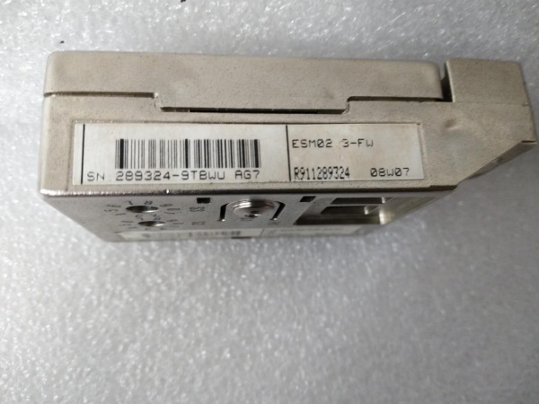
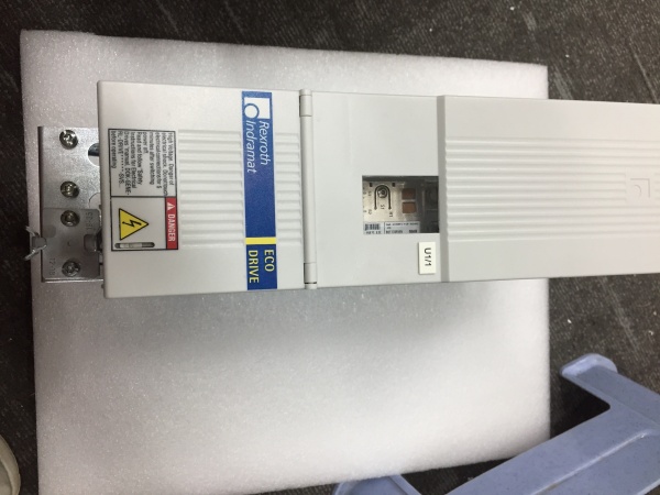
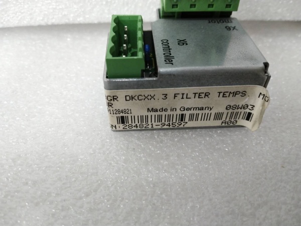
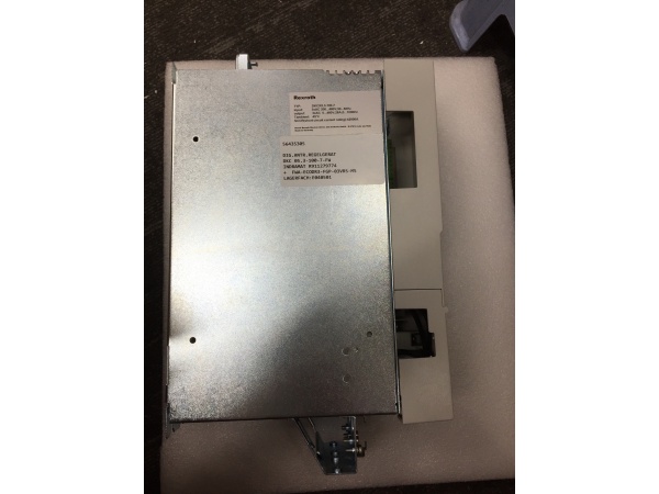
Rexroth DKC11.3-040-7-FW
Where you’ll typically find it:
- CNC machine retrofits upgrading from analog DC drives to AC servo
- Legacy PLC systems with ±10V analog output modules
- Printing presses and paper processing machinery
- Packaging machines using older motion controllers
Bottom line: Get 40A digital servo performance with simple ±10V control—drop into existing analog control systems without fieldbus complexity.
Hardware Architecture & Under-the-Hood LogicThe DKC11.3-040-7-FW is a digital servo drive with an analog command interface. It converts ±10V analog signals into digital position/velocity/torque control loops via its internal DSP while maintaining full digital servo performance.
Internal signal flow:
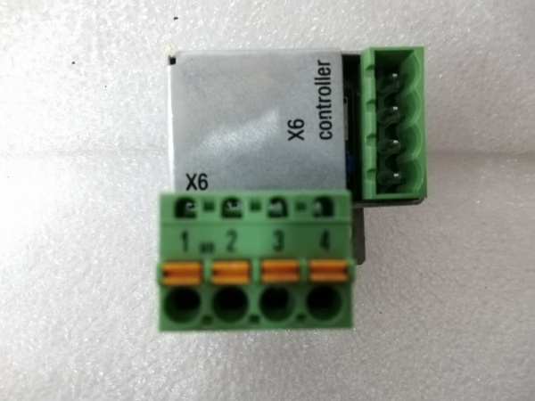
- Analog Input Stage: ±10V command signal enters via terminal block (typically analog input terminals), filtered and conditioned.
- ADC Conversion: Analog-to-digital converter samples the ±10V signal at high rate for digital processing.
- DSP Processing: Digital signal processor executes firmware-defined control loops (position, velocity, torque) based on converted analog command.
- Power Stage Inversion: IGBT inverter generates three-phase PWM output to motor (up to 800V, 40A rated).
- Feedback Processing: Encoder feedback (resolver, incremental, absolute) processed by DSP for closed-loop control.
- Current Regulation: Internal current loops regulate motor current via IGBT gate drive, maintaining torque accuracy.
Rexroth DKC11.3-040-7-FW
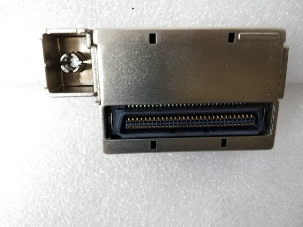
Backplane role: Standalone unit (not backplane-mounted)—connects directly to mains, motor, and control system via terminal blocks and optional external firmware module (ESM slot).
Field Service Pitfalls: What Rookies Get Wrong
Forgetting Analog Input GroundingRookies connect ±10V command without proper grounding, causing erratic motor movement or oscillation.
Field Rule: Use shielded twisted-pair cable for analog command. Ground shield at drive side only (single-point grounding). Verify analog common reference matches PLC/system common—if ground loops exist, use isolation amplifier.
Misconfiguring Analog Command ScalingRookies assume ±10V equals full speed without configuring scale factors, causing overspeed or limited travel.
Quick Fix: Verify analog input scaling parameters in drive firmware. ±10V should correspond to rated motor speed (or torque for torque mode). Test with function generator before connecting live PLC—confirm motor responds correctly to 0V, +10V, -10V inputs.
Overlooking Switching Frequency DeratingRovers set 8kHz for quiet operation without derating, causing drive overheating at 40A load.
Field Rule: Configure switching frequency based on current requirements. 4kHz: Full 40A continuous current available. 8kHz: Continuous current derated to 12.5A only (check datasheet). Use 4kHz for high-current applications—8kHz only for low-current, noise-sensitive environments.
Neglecting Analog Input Offset AdjustmentRovers ignore analog input offset calibration, causing motor creep when command is 0V.
Quick Fix: Perform analog input offset calibration during commissioning. With 0V command applied, verify motor velocity is zero (within spec). If creep exists, adjust offset parameter in firmware or check for ground reference issues.
Forgetting Enable Signal WiringRovers connect analog command but forget drive enable signal, causing drive to ignore commands entirely.
Field Rule: Verify enable signal wiring (typically 24V digital input). Enable must be active before analog commands are accepted. Test enable function independently—drive should show “ready” status only when enable is applied.
Commercial Availability & Pricing Note
Please note: The listed price is for reference only and is not binding. Final pricing and terms are subject to negotiation based on current market conditions and availability.


