
Description
Hard-Numbers: Technical Specifications
| Parameter | Specification |
|---|---|
| Manufacturer | Bosch Rexroth Indramat |
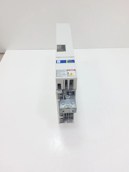
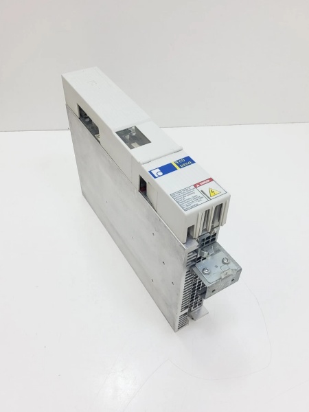
| Part Number | DKC11.1-040-7-FW |
| MPN | R911269392 |
| Series | DKC Series (EcoDrive), Version 1 |
| Drive Type | Digital Intelligent AC Servo Drive Controller |
| Rated Current | 40 A |
| Peak Current | 40 A |
| Making Current | 9 – 12 A |
| DC Bus Nominal Voltage | 700 V |
| DC Bus Voltage Range | 500 – 800 V |
| DC Bus Capacitance | 0.15 mF |
| Communication Interface | Analog (with optional positioning interface) |
| Serial Interface | RS232/RS485 (connector X2) |
| Mains Input Voltage | 3 x AC (380 – 480) V ±10% |
| Mains Frequency | 50/60 Hz |
| Maximum Continuous Current (4 kHz) | 11 A |
| Maximum Continuous Current (8 kHz) | 12.5 A |
| Maximum Output Frequency (4 kHz) | 400 Hz |
| Maximum Output Frequency (8 kHz) | 800 Hz |
| Rated Control Voltage | DC 24 V ±10% |
| Control Voltage Current Consumption | 0.7 A |
| Holding Brake Voltage | DC (19.2 – 28.8) V |
| Holding Brake Current Consumption | DC 24 V ±10% |
| Switching Frequency | Selectable: 4 kHz or 8 kHz |
| Power Dissipation (without bleeder) | 180 W |
| Peak Bleeder Output | 10 kW (for 1 s) |
| Continuous Bleeder Output | 5 kW |
| Maximum Feedback Energy | 15 kWs |
| Storage Energy (DC Bus) | 0.15 kWs |
| Cooling Method | Internal air blower (for DKC01.1-040-7-FW variant) |
| Enclosure Protection | IP 20 |
| Pollution Degree | 2 (per EN 50178) |
| Operating Temperature Range | 0°C to +40°C (rated data) |
| Storage/Transport Temperature | -20°C to +80°C |
| Maximum Installation Elevation | 1000 m |
| Maximum Relative Humidity | 90% non-condensing |
| Dimensions (L × H × W) | 360 mm × 210 mm × 65 mm (14.2″ × 8.3″ × 2.6″) |
| Weight | 4.4 kg (9.7 lbs) |
| Positioning Blocks | Up to 32 |
| Firmware | FW A-ECODRV-ASE-02VRS-MS (sold separately) |
| Voltage Category | 7 |
| Compliance | UL 508 C, CSA C22.2 No. 14-05 |
| Compatible Motors | MKD digital AC motors |
| SCCR | 42,000 A rms |
DKC11.3-040-7-FW
The Real-World Problem It Solves
Industrial automation demands cost-effective digital intelligence without sacrificing precision or reliability. The DKC11.1-040-7-FW delivers a 40A-rated servo drive with analog interface, 700V DC bus architecture, and integrated position control—enabling efficient energy management, rapid response in high-speed applications, and seamless integration with existing control systems. Its modular EcoDrive design supports up to 32 stored positioning blocks, software travel limit switches, automatic parameter matching, and extensive diagnostics via DriveTop software—all while maintaining a price-to-performance ratio ideal for budget-conscious automation projects.
Where you’ll typically find it:
- Handling systems and assembly equipment with analog control signals
- Packaging machinery requiring precise positioning with cost-effective drives
- Printing machines and processing equipment with analog interface requirements
- CNC machine tools with servo axes using analog ±10V commands
- Automated assembly lines and material handling systems
- Retrofit projects requiring analog drive compatibility
- Single-axis and multi-axis drive applications where distributed intelligence is beneficial
Bottom line: This is an economical digital intelligent automation system offering highest functionality for almost any field requiring translatory or rotary motion automation—with universal implementation, lower total costs, digital drive concept, highly dynamic operation, cost-effective direct connection to power mains, and integrated features like software travel limit switch, absolute or incremental position detection, and automatic parameter matching.
Hardware Architecture & Under-the-Hood Logic
The DKC11.1-040-7-FW is a digital intelligent AC servo drive controller based on the Indramat EcoDrive architecture. It combines microprocessor control with analog interface connectivity to deliver precise three-phase AC motor control, integrated position control, and extensive diagnostic capabilities.
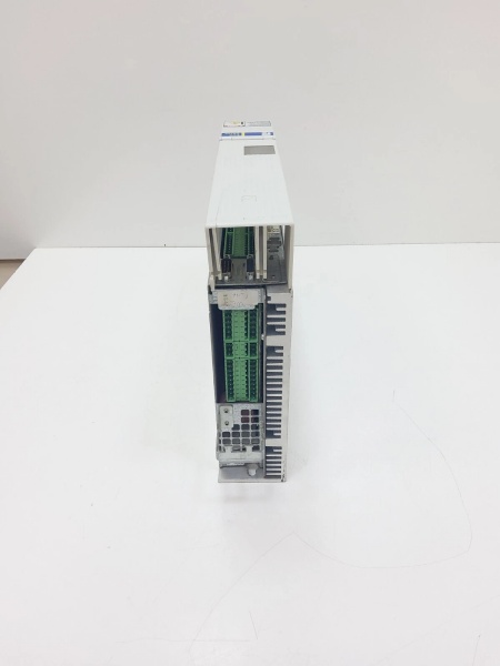
- Power Stage – Three-phase IGBT-based power inverter generating 40A rated output for MKD digital AC servo motors
- DC Link Circuit – 700V nominal DC bus with 0.15 mF capacitance, receiving power from mains via direct three-phase connection
- Digital Signal Processor (DSP) – Microprocessor core executing current, speed, and position control loops with selectable 4 kHz or 8 kHz switching frequency
- Analog Interface – Traditional ±10V velocity/torque command interface for compatibility with legacy control systems
- Positioning Interface (optional) – Integrated position control storing up to 32 positioning blocks for independent motion sequence execution
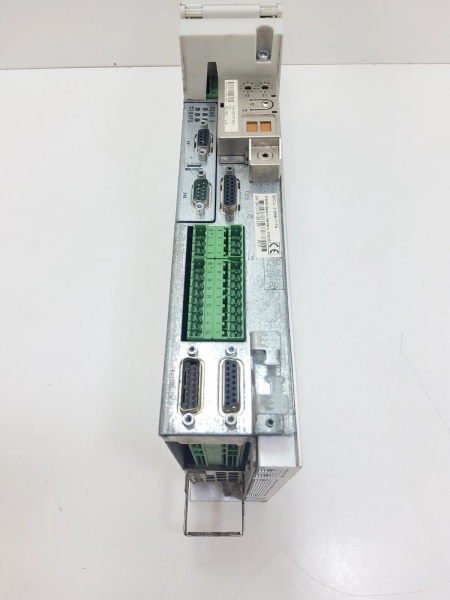
- RS232/RS485 Interface (X2) – Serial communication ports for DriveTop commissioning software and diagnostics
- Parameter Module – Non-volatile memory for drive parameters, motor settings, positioning blocks, and configuration data
- Programming Module – Contains diagnostic display (H1), reset button (S1), and interface for parameter configuration
- Terminal Block X1 – Control voltage connections (24V supply, emergency stop, enable signals)
- Terminal Block X3 – Digital and analog I/Os for limit switches, reference switches, and auxiliary signals
- Terminal Block X4 – Encoder connection (motor feedback interface for digital encoders)
- Terminal Block X5 – Motor connections (U, V, W phases), DC bus connections, and mains input (3-phase 380-480V)
- Terminal Block X6 – Motor temperature monitoring (TM+, TM-) and holding brake control
- Terminal Block X8 – Direct three-phase mains power connection (380-480V input)
- Terminal Block X9 – Incremental and absolute encoder emulation in SSI format
- Terminal Block X10 – Ecox expansion interface for additional functionality
- Soft-Start Circuitry – Reduces inrush current during power-up with making current 9-12A
- Bleeder Resistor Control – Regenerative energy dissipation during deceleration via external braking resistors
- Overcurrent Protection – Fast-acting current limiting and fault detection protecting motor and drive
- Overtemperature Protection – Thermal sensors monitoring heatsink and power stage temperatures (F218 fault code)
- UnderVoltage/OverVoltage Protection – DC bus voltage monitoring preventing operation outside safe limits (500-800V range)
- Motor Temperature Evaluation – Processes temperature-dependent resistor signals from Rexroth motors (F219 fault code)
- Holding Brake Control – Integrated output controlling electromagnetic brakes on motors with brakes
- Diagnostic Display (H1) – 7-segment LED display showing fault codes, status information, and diagnostics
- Reset Button (S1) – Manual reset button for clearing faults and restarting drive
- Enable Logic – Two-channel enable circuitry requiring proper enable signal sequencing for motor power
- Emergency Stop Integration – Dedicated emergency stop input for safe shutdown
- Software Travel Limit – Programmable software-based travel limit switches preventing mechanical overtravel
- Automatic Parameter Matching – Automatic adjustment of drive parameters to motor and system characteristics
- Adjustable Error Response – Configurable error response behaviors improving system reliability
- Internal Air Blower (DKC01.1 variant) – Forced-air cooling system ensuring thermal stability during continuous operation
- EMC Filter – Integrated electromagnetic compatibility filtering for compliance with EN 50081-2
- PE Connections – Protective conductor connections for motor and mains grounding
DKC11.3-040-7-FW
Field Service Pitfalls: What Rookies Get Wrong
Confusing DKC11.1 with DKC01.1
DKC11.1-040-7-FW and DKC01.1-040-7-FW share similar technical data but differ in communication interface. Rookies treat them as identical units—DKC11.1 features analog interface only, while DKC01.1 supports analog, stepper motor, and positioning interfaces.
Field Rule: Verify model number and communication interface before installation or replacement. DKC11.1: analog interface only, designed for applications using ±10V velocity/torque commands from PLCs or CNC controls. DKC01.1: supports additional interfaces including positioning blocks and stepper motor control. Cross-reference model compatibility lists before procuring replacement units—installing wrong variant causes communication failures and system incompatibility.
Neglecting Mains Voltage Range (380-480V)
DKC11.1-040-7-FW requires 3-phase AC input (380-480V) with ±10% tolerance. Rookies attempt connection to 230V single-phase supplies or voltages outside this range, causing drive faults, inability to start, or permanent damage.
Quick Fix: Verify mains voltage matches 380-480V three-phase specification before connection. If site has 230V supply, use autotransformer or isolation transformer to step up to required voltage. Measure actual voltage with multimeter during commissioning to ensure it’s within ±10% tolerance. Document voltage readings in maintenance log—fluctuations outside range cause intermittent operation.
Forgetting Firmware Specification on Orders
“FW” suffix indicates firmware specifying drive functions—sold separately from base drive. Rookies order DKC11.1-040-7-FW without specifying firmware (ASE02 or ASE04), receiving unit without proper control functions or incompatible firmware version.
Field Rule: Always specify firmware version when ordering DKC11.1-040-7-FW. Two major firmware types: ASE02 and ASE04—each supporting different feature sets. Check existing firmware label on unit before ordering replacement. Firmware determines available features: positioning blocks, error response behaviors, parameter matching functions. After installation, verify firmware version using DriveTop software or diagnostic display.
Overlooking Switching Frequency Selection (4 kHz vs 8 kHz)
DKC11.1-040-7-FW offers selectable switching frequency: 4 kHz or 8 kHz. Rookies leave setting at default without considering application requirements, causing excessive audible noise (4 kHz) or reduced efficiency (8 kHz in some applications).
Quick Fix: Select switching frequency based on application requirements during parameter configuration. 4 kHz: higher torque output, more audible noise, suitable for low-speed high-torque applications. 8 kHz: reduced torque, quieter operation, better efficiency at high speeds. Use DriveTop software to adjust switching frequency parameter. Test motor performance after adjustment—verify torque output and noise levels meet application requirements.
Ignoring DC Bus Discharge Time
DKC11.1-040-7-FW contains capacitors storing high DC bus voltage (up to 800V). Rookies open covers or touch terminals within minutes of disconnecting power, risking fatal electric shock.
Field Rule: After disconnecting main power and control voltage, wait minimum 5 minutes (DC bus capacitance 0.15 mF) before touching any electrical components. Verify DC bus voltage has discharged below 50V using a properly rated multimeter before beginning maintenance work. Although DKC11.1 has smaller capacitance than larger drives (0.15 mF vs 0.27 mF for DKC03.3), always measure voltage to confirm discharge.
Misconfiguring Analog Interface Scaling
Analog interface requires proper scaling of ±10V command signal to velocity or torque setpoints. Rookies use default scaling values without verifying motor requirements, causing incorrect speed/torque response or erratic motion.
Quick Fix: Configure analog interface scaling in DriveTop parameters. Verify ±10V input maps to correct velocity range for application (e.g., -10V = -3000 rpm, +10V = +3000 rpm). Test analog command signals with calibrated voltage source before connecting to PLC/CNC. Document scaling parameters for each axis—critical for predictable motion control behavior.
Neglecting Motor Temperature Monitoring
DKC11.1-040-7-FW evaluates motor temperature via TM+/TM- connections (X6). Rookies leave temperature monitoring disconnected or miswired, eliminating thermal protection for motor—risking motor overheating and permanent damage (F219 fault code).
Field Rule: Connect motor temperature sensor to X6 terminals: TM+ to temperature sensor positive, TM- to temperature sensor negative. Verify temperature signal in DriveTop diagnostics—should read motor temperature in degrees Celsius. Test thermal protection by inducing controlled overload—drive should fault or derate when motor temperature exceeds limits. Document temperature monitoring setup for preventive maintenance.
Forgetting Bleeder Resistor Sizing
During deceleration or axis lowering, motor regenerates energy into DC link. Rookies operate drives without properly sized braking resistors or connect resistors with incorrect resistance/wattage, causing DC link overvoltage faults or resistor burnout.
Quick Fix: Install braking resistor sized for application regenerative energy (calculate based on axis inertia, deceleration rate, duty cycle). Peak bleeder output: 10 kW (for 1 s), continuous: 5 kW. Ensure braking resistor has adequate thermal rating and airflow. Test deceleration profiles and monitor DC link voltage; if overvoltage occurs, increase braking resistor wattage or reduce deceleration rates. Verify bleeder resistor connections match DKC11.1 specifications.
Improper RS232 Cable Connection
DriveTop communicates via RS232 serial port (X2). Rookies use wrong cable type or USB-to-Serial adapters with incompatible drivers, resulting in “communication failed” errors in DriveTop software.
Field Rule: Use official Bosch Rexroth interface cable for DKC11.1 drives. If using USB-to-Serial adapter, ensure drivers are installed and COM port is recognized in Windows Device Manager. In DriveTop, verify COM port selection matches adapter assignment. Test cable with multimeter for continuity if connection fails—pinout mismatch is common cause of communication issues. RS485 interface also available via X2 for multi-drop configurations.
Misdiagnosing Fault Codes Without DriveTop Diagnostics
DKC11.1-040-7-FW displays fault codes on H1 7-segment display. Rookies interpret fault codes based on incomplete documentation, replacing components unnecessarily when root cause is external (mains voltage, encoder failure, mechanical jam).
Field Rule: Use DriveTop software to read complete diagnostic buffer, not just single fault code displayed on H1. Diagnostic buffer shows fault history, multiple faults, and detailed error descriptions. Common fault patterns: F218 (heatsink overtemperature), F219 (motor overtemperature), F228 (excessive control deviation), F00xx (overcurrent), F01xx (overvoltage). Cross-reference faults with mechanical system—often drive faults indicate external problems (seized bearing, cable short, brake failure, temperature sensor malfunction).
Overlooking Installation Clearance Requirements
DKC11.1-040-7-FW requires proper clearance for cooling and maintenance access. Rookies mount drives too close to cabinet walls or other equipment, obstructing airflow and causing overheating.
Quick Fix: Maintain minimum clearance per dimension sheet: top: 150 mm (for cooling exhaust), bottom: 80 mm (for cooling inlet), sides: 50 mm for maintenance access. Ensure cooling air inlet (bottom) is unobstructed and warm air outlet (top) has clear path to cabinet exhaust. Monitor drive temperature during initial commissioning—if drive overheats despite proper clearance, verify cabinet ambient temperature and consider additional cooling fans.
Commercial Availability & Pricing Note
Please note: The listed prices are for reference only and are not binding. Final pricing and terms are subject to negotiation based on current market conditions, product condition (new vs. refurbished), and supplier.


