
Description
Hard-Numbers: Technical Specifications
| Parameter | Specification |
|---|---|
| Manufacturer | Bosch Rexroth Indramat |
| Part Number | DKC03.3-040-7-FW |
| Series | EcoDrive03 (DKC Series, Version 3) |
| Drive Type | Digital Intelligent AC Servo Drive Controller |
| Rated Current (Output) | 40 A |
| Type Current | 040 (16A continuous, 40A peak) |
| DC Bus Nominal Voltage | 700 V |
| DC Bus Voltage Range | 500 to 800 V DC |
| Communication Interface | PROFIBUS-DP |
| Input Voltage Range | 200 to 480 V AC (±10%) |
| Input Phases | 1 × AC or 3 × AC supported |
| Input Frequency Range | 50 to 60 Hz (±2 Hz) |
| Maximum Input Current | 16 A |
| Maximum Output Voltage | 800 V |
| Maximum Output Frequency | 1000 Hz (400 Hz at 4 kHz, 800 Hz at 8 kHz) |
| Rated Control Voltage | 24 V DC |
| Cooling Method | Internal blower cooling |
| Enclosure Protection | IP 20 |
| Operating Temperature Range | 0°C to +45°C (rated data) / up to +55°C (derated) |
| Storage/Transport Temperature | -30°C to +85°C |
| Maximum Installation Elevation | 1000 m (rated) / up to 2000 m (derated) |
| Maximum Relative Humidity | 95% non-condensing |
| Maximum Absolute Humidity | 25 g/m³ |
| Pollution Degree | 2 (per EN 50178) |
| Power Dissipation | 180 W (at continuous output current) |
| Continuous Bleeder Power | 0.15 kW |
| Maximum DC Bus Charge | 5 kWs |
| Nominal DC Bus Capacitance | 0.27 mF (±20%) |
| Dimensions (H × W × D) | 360 mm × 65 mm × 261 mm (14.2″ × 2.6″ × 10.3″) |
| Weight | 5.7 kg (12.6 lbs) |
| Mounting | Vertical mounting in control cabinet |
| Positioning Blocks | Up to 64 stored blocks |
| Soft-Start Resistor Power | 0.15 kW |
| SCCR (Short Circuit Current Rating) | 42,000 A rms |
| Compliance | UL 508 C, CSA C22.2 No. 14-05 |
| Compatible Motors | MKD, MHD digital AC motors |
| Diagnostic Interface | RS232/RS485 (X2) |
| Firmware | Sold separately (must specify drive functions) |
| Voltage Category | 7 |
| Minimum Top Clearance | 150 mm (for cooling) |
| Minimum Bottom Clearance | 80 mm (for cooling) |
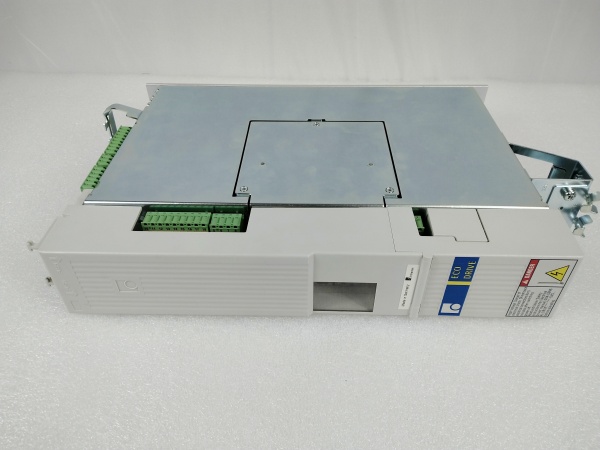
REXROTH DKC03.3-040-7-FW
The Real-World Problem It Solves
Modern industrial automation demands decentralized intelligence, multi-axis coordination, and seamless integration with PLC/HMI systems. The DKC03.3-040-7-FW delivers a 40A-rated servo drive with integrated position control, PROFIBUS-DP communication, and 700V DC bus architecture—enabling fast, torque-sensitive automation cycles, precise positioning sequences, and distributed intelligence that offloads the PLC’s computational burden. Its modular EcoDrive03 design supports up to 64 stored positioning blocks, internal execution of motion programs (point-to-point moves, cam profiles, gearing), and extensive diagnostics via DriveTop software.
Where you’ll typically find it:
- CNC machine tool axes requiring precise positioning
- Handling systems and assembly equipment with coordinated motion
- Packaging machinery with rapid cycle times and complex motion profiles
- Printing presses with registration control and web tensioning
- Conveyor systems with distributed position control
- Industrial robotics and pick-and-place applications
- Roll-feed systems and bending machines
- Multi-axis drive packages with centralized power supply
Bottom line: This is a cost-effective digital intelligent automation system offering high-level functionality, compact modular design, distributed intelligence for position control execution, and seamless PROFIBUS integration—making it ideal for single and multiple-axis drive tasks requiring precise motion control with reduced PLC computational load.
Hardware Architecture & Under-the-Hood Logic
The DKC03.3-040-7-FW is a digital intelligent AC servo drive controller based on the Indramat EcoDrive03 architecture. It combines microprocessor control with modular construction to deliver precise three-phase AC motor control, integrated position control, and fieldbus communication.
- Power Stage – Three-phase IGBT-based power inverter generating 40A rated output for MKD/MHD digital AC servo motors
- DC Link Circuit – 700V nominal DC bus with 0.27 mF capacitance, receiving power from mains supply or shared DC bus configuration
- Digital Signal Processor (DSP) – Microprocessor core executing current, speed, and position control loops with high bandwidth for dynamic response
- PROFIBUS-DP Interface Module – Fieldbus communication enabling cyclic data exchange with PLCs/HMI systems, supporting distributed control architecture
- RS232/RS485 Interface (X2) – Serial communication ports for DriveTop commissioning software and diagnostics
- Integrated Position Controller – Firmware-enabled position control storing up to 64 positioning blocks, executing motion sequences independently from PLC
- Parameter Module – Non-volatile memory for drive parameters, motor settings, positioning blocks, and configuration data
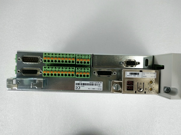
- Programming Module – Contains diagnostic display (H1), reset button (S1), and address switches (S2, S3) for PROFIBUS node addressing
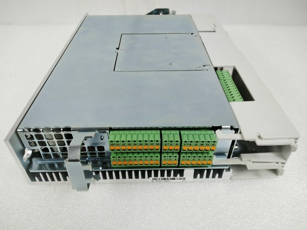
- Terminal Block X1 – Control voltage connections (24V supply, emergency stop, enable signals)
- Terminal Block X3 – Digital and analog I/Os for limit switches, reference switches, and auxiliary signals
- Terminal Block X4 – Encoder 1 connection (motor feedback interface for digital encoders like EnDat, HIPERFACE)
- Terminal Block X5 – Motor connections (U, V, W phases), DC bus connections, and mains input
- Terminal Block X6 – Motor temperature monitoring (TM+, TM-) and holding brake control
- Terminal Block X10 – Ecox expansion interface for additional functionality
- Terminal Block X11 – DC bus dynamic brake (ZKS) and U power supply connections
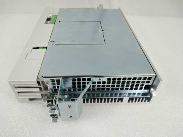
- Internal Blower – Forced-air cooling system ensuring thermal stability during continuous operation
- Soft-Start Circuitry – Reduces inrush current during power-up, protecting mains supply and drive
- Bleeder Resistor Control – Regenerative energy dissipation during deceleration via internal or external braking resistors
- Overcurrent Protection – Fast-acting current limiting and fault detection protecting motor and drive
- Overtemperature Protection – Thermal sensors monitoring heatsink and power stage temperatures, triggering derating or shutdown
- UnderVoltage/OverVoltage Protection – DC bus voltage monitoring preventing operation outside safe limits (500-800V range)
- Motor Temperature Evaluation – Processes temperature-dependent resistor signals from Rexroth motors to prevent thermal damage
- Holding Brake Control – Integrated output controlling electromagnetic brakes on motors with brakes
- Diagnostic Display (H1) – 7-segment LED display showing fault codes, status information, and diagnostics
- Address Switches (S2, S3) – Two decade rotary switches setting PROFIBUS node address (must match PLC configuration)
- Reset Button (S1) – Manual reset button for clearing faults and restarting drive
- Enable Logic – Two-channel enable circuitry requiring proper enable signal sequencing for motor power
- Emergency Stop Integration – Dedicated emergency stop input for safe shutdown per IEC 61800-5-2
- EMC Filter – Integrated electromagnetic compatibility filtering for compliance with EN 50081-2
- PE Connections (XE1, XE2) – Protective conductor connections for motor and mains grounding
REXROTH DKC03.3-040-7-FW
Field Service Pitfalls: What Rookies Get Wrong
Ignoring 30-Minute DC Bus Discharge Time
DKC03.3-040-7-FW contains large capacitors storing lethal DC bus voltage (up to 800V) even after power-off. Rookies open covers or touch terminals within minutes of disconnecting power, risking fatal electric shock.
Field Rule: After disconnecting main power and control voltage, wait minimum 30 minutes before touching any electrical components. Verify DC bus voltage has discharged below 50V using a properly rated multimeter before beginning any maintenance work. Document discharge time in maintenance log—critical for safety compliance and protecting service personnel.
Misconfiguring PROFIBUS Address Switches
DKC03.3-040-7-FW uses two decade rotary switches (S2, S3) for PROFIBUS node addressing. Rookies set switches incorrectly or forget to match PLC configuration, causing drive communication failures and “node not found” errors.
Quick Fix: Verify PROFIBUS node address in PLC project configuration before setting drive switches. Set S2 (tens digit) and S3 (units digit) to match assigned address. Example: Address 12 = S2 set to 1, S3 set to 2. After setting, cycle drive power and verify PLC recognizes node in diagnostics. Always document address assignments to prevent conflicts during system expansion.
Neglecting 150mm Top Clearance for Cooling
Internal blower requires unobstructed airflow—cool air enters bottom, warm air exits top. Rookies mount drives flush with cabinet ceiling or install directly above other equipment, blocking airflow and causing overheating faults, thermal derating, or premature failure.
Field Rule: Maintain minimum 150mm clearance above drive and 80mm below drive for proper convection cooling. Ensure cooling air inlet (bottom) is unobstructed and warm air outlet (top) has clear path to cabinet exhaust. Monitor drive temperature during initial commissioning—if drive overheats despite proper clearance, verify cabinet ambient temperature and consider additional cooling fans.
Forgetting Firmware Module Purchase
“FW” suffix indicates firmware specifying drive functions—sold separately from base drive. Rookies order drive without specifying firmware, receiving unit without proper control functions (position control, safety functions, fieldbus protocols).
Quick Fix: Always specify firmware version when ordering DKC03.3-040-7-FW. Firmware determines available features: positioning blocks, PROFIBUS protocol version, safety functions (STO, SS1, SLS). After installation, verify firmware version using DriveTop software or diagnostic display. Document firmware version for compatibility checks during system upgrades.
Using Incompatible DriveTop Software Version
DKC03.3-040-7-FW requires DriveTop versions 5-16. Rookies attempt connection with older DriveTop versions (1-4) designed for Type 1 drives, causing communication failures or inability to display/modify parameters.
Field Rule: Verify DriveTop version compatibility before attempting connection. Use DriveTop 16VRS (latest) for DKC03.3 drives—backward compatible with most Type 3 units. For very old Type 1 drives (DKC01.1-030-3-FW), use DriveTop versions 1-4. Always use official Bosch Rexroth interface cables (IKB005 for DKC03.3) rather than generic null-modem cables to ensure proper wiring.
Incorrect RS232 Cable Connection
DriveTop communicates via RS232 serial port (X2). Rookies use wrong cable type or USB-to-Serial adapters with incompatible drivers, resulting in “communication failed” errors in DriveTop software.
Quick Fix: Use official Bosch Rexroth IKB005 cable for DKC03.3 drives. If using USB-to-Serial adapter, ensure drivers are installed and COM port is recognized in Windows Device Manager. In DriveTop, verify COM port selection matches adapter assignment. Test cable with multimeter for continuity if connection fails—pinout mismatch is common cause of communication issues.
Overlooking Parameter Module Replacement Compatibility
Parameter modules store drive configuration. Rookies replace parameter modules without verifying hardware/firmware compatibility, causing “parameter mismatch” faults or system incompatibility after module swap.
Field Rule: Before replacing parameter module, verify hardware revision and firmware version compatibility between old and new modules. Use DriveTop software to backup all parameters from old module before removal. After installing new module, restore parameters from backup and verify drive operation. If parameters don’t load successfully, check parameter module compatibility in technical documentation.
Ignoring Motor Temperature Monitoring Connections
DKC03.3-040-7-FW evaluates motor temperature via TM+/TM- connections (X6). Rookies leave temperature monitoring disconnected, eliminating thermal protection for motor—risking motor overheating and permanent damage.
Quick Fix: Connect motor temperature sensor to X6 terminals: TM+ to temperature sensor positive, TM- to temperature sensor negative. Verify temperature signal in DriveTop diagnostics—should read motor temperature in degrees Celsius. Test thermal protection by inducing controlled overload—drive should fault or derate when motor temperature exceeds limits. Document temperature monitoring setup for preventive maintenance.
Misdiagnosing Fault Codes Without Diagnostic Buffer
DKC03.3-040-7-FW displays fault codes on H1 7-segment display. Rookies interpret fault codes based on incomplete documentation, replacing components unnecessarily when root cause is external (mains voltage, encoder failure, mechanical jam).
Field Rule: Use DriveTop software to read complete diagnostic buffer, not just single fault code displayed on H1. Diagnostic buffer shows fault history, multiple faults, and detailed error descriptions. Common fault patterns: F00xx (overcurrent), F01xx (overvoltage), F02xx (undervoltage), F03xx (overtemperature), F04xx (encoder faults), F05xx (communication faults). Cross-reference faults with mechanical system—often drive faults indicate external problems (seized bearing, cable short, brake failure).
Improper PROFIBUS Termination
PROFIBUS-DP requires proper termination at network ends. Rookies install DKC03.3-040-7-FW without enabling termination switches (if applicable) or use incorrect termination resistance, causing communication errors, packet loss, or intermittent connectivity.
Quick Fix: Identify if DKC03.3-040-7-FW is at network end—enable termination switch if present. Verify termination resistor (typically 220Ω) is installed at both ends of PROFIBUS segment. Use PROFIBUS diagnostic tools to check signal integrity, noise levels, and cable quality. Replace damaged PROFIBUS cables or connectors if communication is unstable—shield must be grounded at one end only to prevent ground loops.
Neglecting Brake Control for Vertical Axes
Motors with electromagnetic brakes require controlled brake release/engagement sequence. Rookies rely solely on drive brake control without considering vertical axis safety risks—if control voltage fails, motor coasts unbraked causing hazardous uncontrolled movement.
Field Rule: For vertical axes, implement additional mechanical locking, external braking, or counterbalance systems beyond standard motor brake. Drive brake control (X6) alone insufficient for personnel safety on vertical loads. Install safety fences, guards, light curtains, and emergency stops per risk assessment. Verify brake engagement timing using DriveTop diagnostics—ensure brake releases after motor powers up and engages before motor powers down.
Commercial Availability & Pricing Note
Please note: The listed prices are for reference only and are not binding. Final pricing and terms are subject to negotiation based on current market conditions, product condition (new vs. refurbished), and supplier.


