
Description
Hard-Numbers: Technical Specifications
- Control Type: Single-Axis
- Master Communication: PROFIBUS master
- Primary Encoder Option: IndraDyn/Hiperface/1 Vpp/TTL
- Supported Encoders:
- IndraDyn S MSK motors Encoder System (12V supply)
- Sin-cos Encoder (1 Vpp) with Hiperface
- Sin-cos Encoder (1 Vpp) with EnDat 2.1 Interface
- Sin-cos Encoder (1 Vpp) with Reference Track
- Analog Outputs: 2
- Digital Inputs: 7-11 (configurable)
- Digital Outputs: 4
- Encoder Emulation: Yes, absolute and incremental signals (galvanic isolation, no external power required)
- Safety Technology: Safe Motion (S2) – SIL2/Category 3/PL d
- Software Compatibility: Rexroth IndraWorks for PC
- Product Category: C3 according to IEC 61800-3
- Power Consumption: 7.5 W
- Control Cycle Times:
- Current control: 62.5-125 microseconds
- Position control: 250-500 microseconds
- Speed control: 125-250 microseconds
- PWM Frequency: 2-16 kHz (adjustable)
- Inrush Current: 4 A
- SERCOs III Cycle Period: 1000 microseconds
- Dimensions: 103mm (W) × 241mm (H) × 49.5mm (D)
- Operating Environment: IP20 protection class, max 90% relative humidity
- Mounting: Plugs into compatible power section (HMS01, HCS02, HCS03 drive controllers)
- ESD Protection: Required (highly sensitive to electrostatic discharge)
- Firmware: Sold separately (must be purchased and configured individually)
REXROTH CSH01.1C-PB-ENS-NNN-MEM-S2-S-NN-FW
The Real-World Problem It Solves
You need a single-axis servo controller that combines PROFIBUS networking, flexible encoder support, and integrated safety functions without adding external safety relays. The CSH01.1C-PB-ENS-NNN-MEM-S2-S-NN-FW delivers Safe Motion technology, encoder emulation, and multi-protocol communication in one modular control section. It simplifies machine design by eliminating separate safety hardware while providing high-speed control loops for demanding applications.
Where you’ll typically find it:
- CNC machine tools requiring high-precision axis control
- Packaging lines with synchronized motion and safety door interlocks
- Printing and paper processing machines with tension control
- Robotic cells and pick-and-place systems
- Food processing equipment requiring Safe Motion compliance
Bottom line: It’s the brain of IndraDrive servo systems—combining control, communication, safety, and encoder processing into one pluggable module for seamless integration and rapid field replacement.
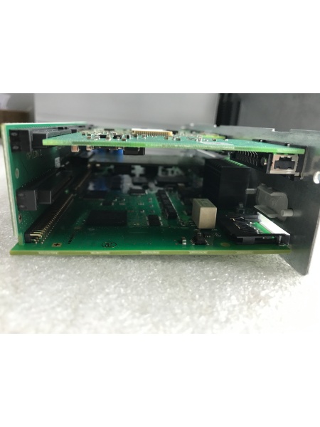
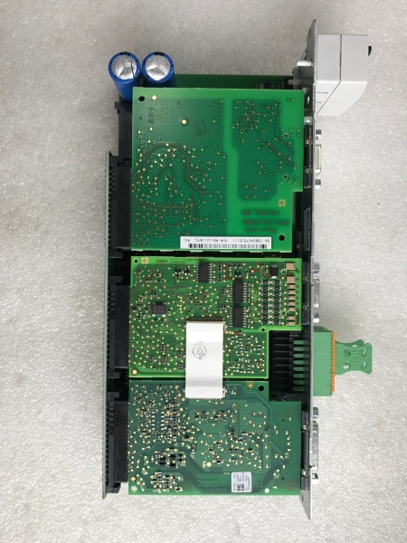
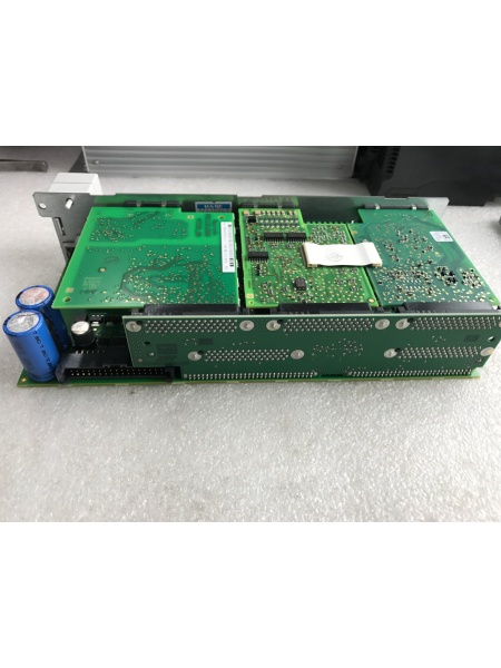
Hardware Architecture & Under-the-Hood Logic
The CSH01.1C control section is a standalone component designed to plug into the power section of Rexroth IndraDrive drive controllers. It houses the motion control processor, communication interfaces, safety circuits, and encoder evaluation logic in a compact, modular package.
- Control Processor (DSP) – High-performance digital signal processor executing current, speed, and position control loops with microsecond cycle times
- PROFIBUS Master Module – Handles network communication, exchanging process data and commands with PLCs or higher-level controllers
- Primary Encoder Interface – Evaluates IndraDyn/Hiperface, 1 Vpp/TTL, sin-cos encoders with optional EnDat 2.1 support
- Encoder Emulation Circuit – Generates galvanically isolated absolute and incremental encoder signals without external power supply
- Safety Technology Module (S2) – Implements Safe Motion functions including safe maximum speed, safe direction, and safe door locking (SIL2/Cat 3/PL d)
- Analog Output Section – Two 12-bit analog outputs (typically ±10V) for external monitoring or control
- Digital I/O Section – Configurable digital inputs and outputs for limit switches, enable signals, and status feedback
- Standard Control Panel Interface – H1 connector for VCP01 comfort control panel or standard display module
- Multimedia Card Slot (X7) – Accepts PFM02.1 MultiMediaCard for parameter backup and firmware updates
- Engineering Interface (X26) – RS232/RS485 serial port for PC-based configuration via IndraWorks software
- Power Supply Circuitry – Internal DC/DC converters generating ±15V, +5V, and +3.3V for logic and I/O circuits
- Terminal Block Connectors – Spring terminals and screw terminal blocks for reliable field wiring connections
- Isolation Circuits – Opto-isolated digital inputs/outputs to prevent ground loops and noise interference
- Watchdog Timer – Monitors processor operation and triggers safe shutdown on fault detection
- Memory System – Non-volatile memory for parameter storage, fault history, and application data
- ESD Protection Circuits – Input protection against electrostatic discharge during handling and installation
- LED Status Indicators – Power, run, fault, and communication status LEDs for diagnostic visibility
- Cooling System – Natural convection cooling (forced ventilation required within drive cabinet)
- Pluggable Connector System – Detaches from power section for rapid field replacement without rewiring entire drive
- Grounding Reference – Dedicated ground points for proper chassis and signal grounding
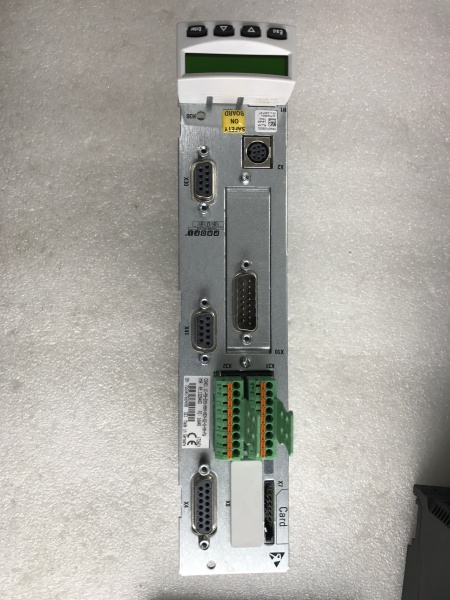
REXROTH CSH01.1C-PB-ENS-NNN-MEM-S2-S-NN-FW
Field Service Pitfalls: What Rookies Get Wrong
Swapping Control Sections Without Firmware Transfer
Newbies pull out a failed CSH01.1C control section and plug in a replacement, assuming parameters will auto-load. The new board ships with factory default firmware and settings. Machine won’t run, or worse—runs at dangerous speeds with wrong parameters. Production halts while they scramble to reconfigure from scratch.
Field Rule: Always backup firmware and parameters before removing any control section. Use Rexroth IndraWorks software to read and save all parameter sets, safety configurations, and application-specific settings. After installing replacement board, load the saved configuration via X26 engineering interface or Multimedia Card. Never assume factory defaults match your machine requirements.
Ignoring ESD Protection During Handling
Rexroth CSH01 control sections are highly sensitive to electrostatic discharge. Field techs grab boards with bare hands, slide them across carpeted floors, or remove them from anti-static bags prematurely. Invisible ESD damage causes intermittent faults weeks later—board works during testing then fails mysteriously under load.
Quick Fix: Keep CSH01.1C in its conductive packaging until you’re ready to install. Touch grounded drive cabinet or wear ESD wrist strap connected to earth ground before handling. Never set the board directly on metal surfaces or workbenches without anti-static mat. If you must temporarily set it down, place it on the original packaging material, not the floor.
Forgetting PROFIBUS Address Configuration
Control sections have unique PROFIBUS addresses that identify them on the network. Rookies swap boards and forget to reprogram the PROFIBUS address to match the failed unit. The PLC can’t communicate, machine won’t start, and they waste hours troubleshooting nonexistent network issues.
Field Rule: Document the PROFIBUS address of the failed control section before removal (displayed on standard control panel or via IndraWorks). Set the new control section to the same address during initial configuration. If your network uses duplicate addresses, you’ll have bus conflicts and unpredictable behavior—always verify addresses are unique across all devices.
Mixing Up Encoder Options
The CSH01.1C-PB-ENS-NNN-MEM-S2-S-NN-FW supports multiple encoder types: IndraDyn/Hiperface, sin-cos with Hiperface, and EnDat 2.1. Newbies connect a different encoder type than configured in parameters, causing “encoder error” fault codes and inability to home or reference the axis.
Quick Fix: Verify which encoder type your motor uses before installing the replacement control section. Check the encoder cable markings and motor documentation. Match the encoder option in parameter settings (usually under encoder configuration menu). If switching from EnDat to Hiperface or vice versa, you must change both hardware connections and software parameters—never mix them.
Neglecting Safe Motion Configuration
The S2 Safe Motion option provides integrated safety functions like safe maximum speed, safe direction, and safe door locking. Rookies ignore these settings during replacement, leaving safety functions unconfigured or disabled. This violates safety standards and creates hazardous machine conditions.
Field Rule: Safe Motion parameters are critical for SIL2/Cat 3/PL d compliance. After installing the new control section, verify Safe Motion functions are enabled and configured according to your machine safety assessment. Test all safety inputs and outputs (via X41 connector) before returning machine to production. Never bypass safety functions for faster troubleshooting—use them to protect operators and equipment.
Powering Up Without Checking Parameter Backup
Newbies restore power immediately after swapping control sections, hoping for the best. If the parameter load fails or firmware is incompatible, the drive may execute uncontrolled motion or trigger fault codes that require professional reset.
Quick Fix: Power up the replacement CSH01.1C and immediately check the standard control panel for error messages or parameter mismatch warnings. Verify the firmware version matches your saved configuration file. Only after confirming proper parameter loading and no active faults should you enable the drive and test motor operation.
Improper Grounding of Encoder Shields
Encoder cables carry sensitive feedback signals over long cable runs. Rookies connect encoder cables but leave shield wires disconnected or grounded at both ends, creating ground loops that cause erratic position feedback and noisy operation.
Field Rule: Ground encoder cable shields at the control section end only, following Rexroth guidelines. Use proper shielded encoder cables and terminate shields at the designated ground point on the CSH01.1C terminal block. Grounding shields at both ends creates ground loops and introduces noise that degrades positioning accuracy.
Skipping Encoder Calibration After Replacement
After swapping control sections, some encoders require recalibration or homing procedures. Newbies skip this step, assuming the axis is still referenced from previous operation. The machine may not return to proper home position, causing crashes or dimensional errors.
Quick Fix: Always perform a homing or reference run after replacing the control section. Use IndraWorks or the standard control panel to execute the homing sequence according to your machine procedure. Verify the axis reaches the correct mechanical reference before enabling automatic operation. Document the homing offset values for future reference.
Overlooking Analog Output Configuration
The CSH01.1C provides two analog outputs for external monitoring or control. Rookies leave these outputs at default settings, missing critical data signals needed by external controllers or displays.
Field Rule: Configure analog outputs according to your application requirements. Common uses include outputting actual speed, torque feedback, or position for PLC monitoring or external instrumentation. Set scaling and offset values in IndraWorks to match external device input ranges. Test analog outputs with a multimeter during commissioning to verify accuracy.
Commercial Availability & Pricing Note
Please note: The listed prices are for reference only and are not binding. Final pricing and terms are subject to negotiation based on current market conditions and availability.


