
Description
Hard-Numbers: Technical Specifications
- Number of Channels: 3 independent servo control channels (CH1, CH2, CH3)
- Encoder Input Type: Incremental pulse encoder (2-phase with 90° phase difference)
- Z-Pulse Support: Yes, with latch signal capability
- Latch Inputs: Mark signal and origin point latch inputs per channel
- Analog Output Range: ±8V or ±10V
- Pulse Encoder Input Types Supported:
- 5V differential output type
- 12V emitter follower output type
- 12V open collector output type
- 12V totem pole output type
- Not Supported: 5V emitter follower, open collector, or totem pole type (requires signal conditioning)
- Maximum Response Frequency: 300 kHz (1.2 MPPS with multiplier of 4)
- Input Impedance: ~200Ω for 5V differential input at 2.5V; ~1kΩ for 12V input
- Isolation: Photo-isolators separate pulse input circuits from internal circuits
- Programming Environment: Same as AutoMax System (binary compatible with PSC3000)
- Operating System Storage: Flash memory (flash ROM)
- OS Download Sources: PSC4000 Programming Terminal or IC Memory Card
- Battery: On-board battery for program retention
- Battery Status Threshold: 2.5V (BAT.OK LED ON at ≥2.5V)
- Memory Card Support: IC Memory Card for program backup and loading
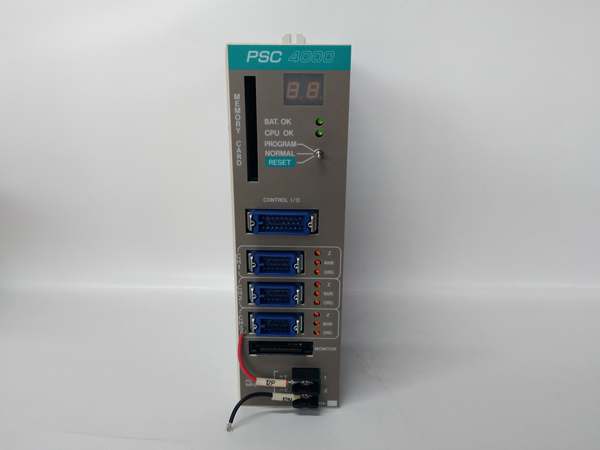
- Mounting Slot: Slot 0 on PSC4000 Base Unit
- Status Display: Two yellow seven-segment LEDs for diagnostic codes
- Latch Status Indicators: Orange LEDs (Z, MARK, ORG) per channel

RELIANCE WR-D4004
The Real-World Problem It Solves
Multi-axis servo coordination demands high-speed encoder processing, precise analog output generation, and rock-solid program retention. This card handles three independent axes with encoder processing up to 300 kHz, configurable latch modes for homing and registration, and ±10V outputs driving your servo amplifiers. The on-board battery keeps your motion programs safe through power cycles.
Where you’ll typically find it:
- PSC4000 Programmable Servo Controller Systems (3-axis configuration)
- PSC3000 System applications (binary compatible with PSC3000 OS)
- CNC machinery for multi-axis coordinate control
- Packaging equipment requiring synchronized motion control
- Robotics and material handling systems
Bottom line: It’s the motion control brain of your PSC4000 system—feed it clean encoder signals, keep that battery fresh, and it’ll hold sub-millisecond positioning accuracy for years.
Hardware Architecture & Under-the-Hood Logic
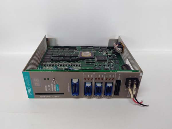
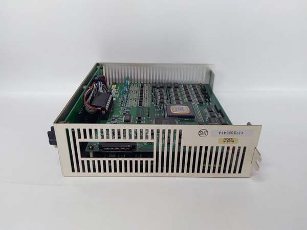
The WR-D4004 is a multi-axis servo control card that plugs into slot 0 of the PSC4000 Base Unit. It processes incremental encoder inputs, executes servo control algorithms, and generates analog outputs for servo amplifiers across three independent channels.
- Power supplied from PSC4000 Base Unit through backplane connector
- On-board battery provides memory backup for user programs during power loss or card removal
- Battery monitoring circuit continuously checks battery voltage (2.5V threshold for BAT.OK LED)
- Flash memory stores operating system (PSC3000-compatible)
- Processor executes servo control algorithms and application programs
- CPU OK LED illuminates when processor is operating normally
- Two yellow seven-segment LEDs display self-diagnostic error codes and run-time status
- System switch selects PROGRAM or NORMAL mode, provides system reset function
- For program loading from IC Memory Card: insert card with label side facing system switch
- Press system switch downward for 3+ seconds to reset and auto-load program from IC Memory Card
- CONTROL I/O connector provides mark/origin point latch inputs and ±8V/±10V analog outputs for all 3 channels
- CH1/CH2/CH3 connectors each provide independent encoder input and analog output
- Pulse encoder power input terminals supply power to external encoders connected to CH1-CH3
- Pulse Input Circuit per channel accepts A-phase, B-phase, and Z-pulse signals
- Supports 5V differential OR 12V (emitter follower, open collector, totem pole) inputs
- Separate connector pins for 5V differential vs 12V input types
- Photo-isolators isolate input circuits from internal logic
- Input impedance: ~200Ω (5V differential at 2.5V) or ~1kΩ (12V)
- Maximum response: 300 kHz (1.2 MPPS with 4x multiplier)
- Latch Input Circuit per channel accepts mark signal and origin point signal inputs
- Latches pulse counter based on configurable trigger conditions
- Supports multiple latch modes (rising/falling edge, forward/reverse rotation, Z-pulse combined)
- ORG latch indicator LED illuminates when origin point signal detected
- MARK latch indicator LED illuminates when mark signal detected
- Z latch indicator LED illuminates when Z-pulse detected
- Analog Output Circuit per channel generates ±8V or ±10V analog output for servo amplifier control
- Monitor connector supports optional Monitor Card for signal observation
- Analog Monitor connector (on bottom surface) provides analog voltage representation of Control Block variables
- IC Memory Card slot allows program backup and loading without Programming Terminal
- Counter variables (CHn_COUNTER) track encoder position per channel
- Pulse multiplier variables (CHn_MULT%) allow edge multiplication (1x, 2x, 4x)
RELIANCE WR-D4004
Field Service Pitfalls: What Rookies Get Wrong
Connecting Incompatible 5V Encoder Types
The WR-D4004 accepts 5V differential encoders but NOT 5V emitter follower, open collector, or totem pole types. I’ve seen techs spend days troubleshooting position drift when the real problem was connecting a standard 5V TTL encoder to the wrong pins.
Field Rule: Verify your encoder type before connection. Use 5V differential encoders directly. For 5V emitter follower/open collector/totem pole, use signal conditioners or external line receivers to convert to differential or 12V-compatible signals. Check the encoder datasheet—output type is usually on page 2.
Miswiring 12V Encoder Power
12V encoders require external power supply. Rookies often connect 12V encoder signal wires to the 5V differential pins, resulting in no operation or fried input circuits.
Field Rule: Use the dedicated Pulse Encoder Power Input terminals on the faceplate to supply 12V to your encoders. Connect encoder signal wires to the 12V input pins, not the 5V differential pins. Verify voltage levels with a multimeter before connecting—12V on 5V pins will damage the opto-isolators.
Incorrect Latch Mode Configuration
Latch timing determines your homing and registration accuracy. Leaving latch inputs unconfigured results in missed origin point captures or inconsistent positioning references.
Field Rule: Program the latch input selection variables (CHnZZZ@ for Z-pulse, CHnMRK@ for mark, CHnORG@ for origin) for your application. Refer to Tables 4.1 and 4.2 in the Engineering Manual for available latch mode combinations. Test latch functionality at slow speed before running at full velocity.
Neglecting Battery Maintenance
The on-board battery is your only protection against program loss. I’ve seen entire production lines sit idle for days because a $3 lithium battery died and the motion program was lost.
Quick Fix: Monitor the BAT.OK LED every shift. If it’s OFF, the battery voltage is below 2.5V—replace it immediately. Document battery replacement dates. When replacing, prepare an IC Memory Card backup first; once the battery dies completely, your program is gone.
Using Analog Monitor for Control Purposes
The Analog Monitor connector provides test points, not control outputs. I’ve seen engineers try to drive servo amplifiers from these signals, wondering why the system hunts uncontrollably.
Field Rule: Use the Analog Monitor connector ONLY for observation with oscilloscopes or pen recorders with high input impedance. Never connect to servo amplifier command inputs or control circuits. These signals are not isolated—using them for control risks ground loops and equipment damage.
Incorrect IC Memory Card Insertion
Loading programs from IC Memory Card requires proper card orientation. Rookies insert cards backward or press the system switch incorrectly, causing loading failures or system lockups.
Quick Fix: Insert the IC Memory Card with label side facing the system switch. Press the system switch downward and hold for at least 3 seconds to initiate reset and auto-load. Release the switch—the card will automatically load the program. If loading fails, verify card orientation and that the card contains valid program data.
Ignoring System Switch Mode
PROGRAM vs NORMAL mode selection prevents accidental operation. Leaving the switch in PROGRAM mode during operation causes unexpected behavior or prevents auto-start.
Field Rule: Set the system switch to NORMAL mode for normal operation. Use PROGRAM mode only when loading programs or making configuration changes via Programming Terminal. After program changes, return to NORMAL mode before resuming production.
Forgetting to Verify Encoder Phase
90° phase difference between A and B channels determines direction detection. Reversed A/B connections cause incorrect direction sensing or position drift that gets worse at higher speeds.
Quick Fix: With the encoder connected and system powered, slowly rotate the encoder in one direction. Observe the counter increment direction. Reverse A/B connections if the direction is opposite of expected. Verify direction at multiple speed points—phase errors are most apparent at higher RPM.
Hot-Swapping the Control Card
This card does NOT support hot-swapping. Attempting to remove or insert WR-D4004 while the PSC4000 system is powered causes arcing, card damage, and backplane damage.
Field Rule: ALWAYS power OFF the entire PSC4000 system before inserting or removing the Control Card. Verify zero voltage with a multimeter on power terminals. Use ESD precautions—ground yourself and handle the card by edges only. The backplane carries live DC voltages when powered.
Overlooking Multiplier Settings
The pulse multiplier (CHn_MULT%) affects counting resolution and maximum speed. Leaving it at default may result in insufficient resolution for precision applications or reduced maximum speed.
Quick Fix: Calculate required resolution for your application: resolution = encoder PPR × multiplier. Higher multiplier increases resolution but reduces maximum measurable speed (300 kHz limit). Set multiplier to 1, 2, or 4 as needed. Example: 1000 PPR encoder with 4x multiplier = 4000 counts/rev resolution.
Important Note: Multiple online sources incorrectly describe WR-D4004 as a network router, analog output module, or generic PLC. Based on Engineering Manual 23615-1E, WR-D4004 is definitively a PSC4000/PSC3000 Servo Control Card for multi-axis motion control applications. Trust the manual, not the supplier catalog.
Commercial Availability & Pricing Note
Please note: The listed price is for reference only and is not binding. Final pricing and terms are subject to negotiation based on current market conditions and availability.


