
Description
Hard-Numbers: Technical Specifications
- Input Voltage: 100 VAC nominal
- Input Power Capacity: 170 VA at 100 VAC
- Input Frequency: 50/60 Hz
- Output Voltages: DC voltages for PSC system logic circuitry (specific values not listed in available manual sections)
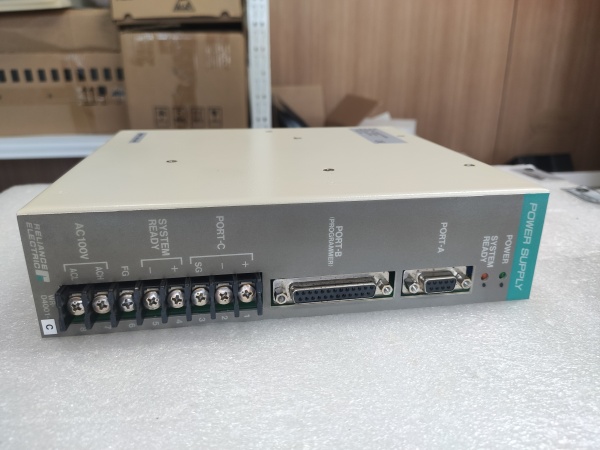
- Communication Ports:
- PORT-A: RS-232C for host computer and Graphic Operation Panel
- PORT-B: RS-232C dedicated for PSC5000 Programming Terminal only
- PORT-C: Terminals for Remote Setter 9 communication
- SYSTEM READY Output: Normally closed contact, opens on shutdown/终止-all
- SYSTEM READY Ratings: 100 VAC or 30 VDC (Europe); 250 VAC or 30 VDC (other regions); Maximum 3A
- Operating Temperature: 0°C to +55°C (32°F to 131°F)
- Terminal Type: M4 screw terminals (require round-type or Y-type crimp contacts)
- Grounding Requirement: Independent grounding required for FG terminal (connected to center of internal noise filter)
- LED Indicators: Green POWER LED, Orange SYSTEM READY LED
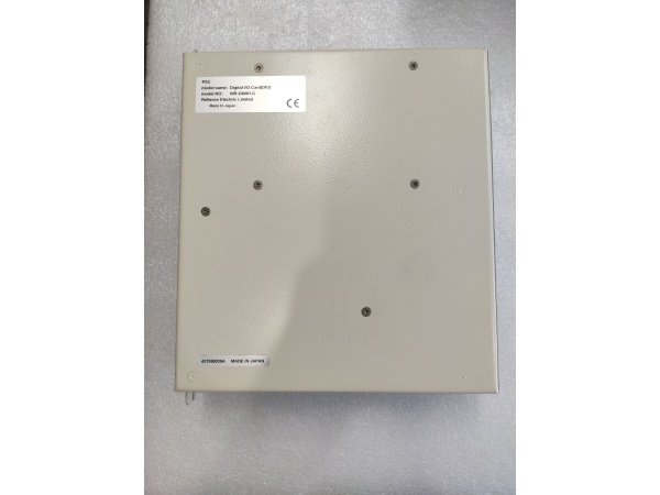
- Certifications: WR-D4001 is NOT UL-listed nor CE Marking compliant (WR-D4007 variant is CE/UL compliant)
- Installation: Plugs into dedicated leftmost slot on PSC Back Plane
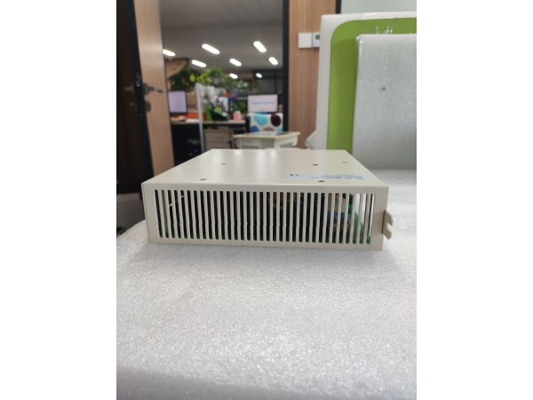
- Protection: Enclosed in protective steel housing with integral heatsink

RELIANCE WR-D4001-A
The Real-World Problem It Solves
Servo control systems demand rock-solid DC power with clean signal handling for programming and monitoring. This card converts raw 100 VAC into multiple regulated DC rails while providing dedicated ports for programming terminals and host communication. The SYSTEM READY contact gives external safety circuits a clean hardware signal that the PSC system is alive and healthy.
Where you’ll typically find it:
- Reliance PSC3000 Programmable Servo Control Systems
- Reliance PSC5000 Programmable Servo Controller Systems
- AutoMax rack assembly systems with servo control requirements
- CNC machinery and packaging equipment requiring precise servo positioning
Bottom line: It’s the power backbone of your PSC servo system—feed it clean 100 VAC, ground it properly, and it’ll keep your servo amps humming for years.
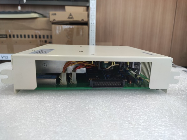
Hardware Architecture & Under-the-Hood Logic
The WR-D4001-A is a power conversion and interface card that lives in the leftmost slot of the PSC backplane. It transforms AC mains into the DC voltages required by all cards in the rack while managing communication ports and monitoring system health through the SYSTEM READY output.
- AC input power (100 VAC) enters through terminals 7 and 8 on terminal block
- Internal EMI/noise filter filters incoming AC power to reduce electrical noise
- FG (frame ground) terminal connects to center of noise filter for independent grounding
- AC/DC converter transforms filtered AC power to multiple DC voltages
- DC voltages are regulated and distributed to PSC system logic circuitry via backplane connector
- Power supply monitoring circuit continuously checks output voltages and system status
- Green POWER LED illuminates when power conversion is operating within normal parameters
- Control signal generation circuit provides memory hold signals during power ON/shutdown
- SYSTEM READY output contact (terminals 4-5) monitors PSC Control Card CPU OK status
- Orange SYSTEM READY LED illuminates when PSC system is normally operating
- SYSTEM READY contact opens when PSC system shuts down or experiences 终止-all condition (~200ms)
- PORT-A RS-232C transceiver provides communication interface for host computer and Graphic Operation Panel
- PORT-B RS-232C transceiver provides dedicated communication port for PSC5000 Programming Terminal only
- PORT-C terminal block provides connection points for Remote Setter 9 communication
- Communication circuits support both user-defined BASIC protocols and MODBUS protocol on PORT-A
- Backplane interface connector delivers DC power and receives system status from Control Card
- Static-sensitive components require ESD precautions during handling and installation
RELIANCE WR-D4001-A
Field Service Pitfalls: What Rookies Get Wrong
Applying Incorrect AC Input Voltage
This card is designed for 100 VAC nominal only. Applying 120VAC or 240VAC will cook the AC/DC converter instantly. I’ve seen this happen on day one of a startup when the electrician grabs the nearest available outlet.
Field Rule: Verify AC supply voltage is 100 VAC nominal before connection. Use a step-down transformer if your facility voltage is 120VAC or higher. Never exceed the specified input voltage range—there’s no internal protection against overvoltage on the primary side.
Incorrect Grounding of FG Terminal
The FG terminal connects to the center tap of the internal noise filter. Connecting it to the same ground as your driving power or skipping it entirely creates ground loops that will haunt you with intermittent faults and encoder noise.
Field Rule: Connect the FG terminal to an independent grounding electrode or a separate grounding point from the driving power ground. Use grounding conductor of 2 square millimeters or larger. This is not optional—noise filters don’t work without proper grounding to a clean earth reference.
Incorrect Connection of SYSTEM READY Output
The SYSTEM READY output is a normally closed contact that opens on system failure. I’ve seen rookie engineers wire it as a status input expecting it to close when the system is healthy, then wonder why their safety circuit never engages.
Field Rule: Remember: the contact is normally closed (ON) when healthy and opens (OFF) on failure. Design your safety logic accordingly. Also verify the voltage and current requirements of the connected circuit do not exceed the ratings (100 VAC or 30 VDC in Europe; 250 VAC or 30 VDC elsewhere; maximum 3A). Use interposing relays if needed.
Connecting Non-Programming Devices to PORT-B
PORT-B is dedicated exclusively for the PSC5000 Programming Terminal. Plugging in laptops, HMI panels, or other serial devices will cause communication conflicts and can damage both the power supply card and the connected equipment.
Field Rule: Only connect the dedicated PSC5000 Programming Terminal to PORT-B. Remove the Programming Terminal during normal operation to prevent electromagnetic interference. Use PORT-A for host computer and HMI connections—it supports both BASIC and MODBUS protocols.
Hot-Swapping the Power Supply Card
This card does NOT support hot-swapping. I’ve seen technicians try to swap cards live to avoid shutting down the line, resulting in arcing, fried backplane traces, and a much longer downtime.
Field Rule: Always turn OFF power to the PSC system before inserting or removing the Power Supply Card. Verify power is completely disconnected using a multimeter before handling the card. The backplane carries live DC voltages when powered, and the edge connector is exposed.
Improper Crimp Terminal Selection
The terminal block uses M4 screw terminals. Using bare wire under the screw or incorrect crimp types causes poor connections that overheat and loosen over time.
Field Rule: Use only round-type or Y-type crimp contacts for M4 screw terminals. Ensure proper crimping tool is used for secure connections. Never insert bare wire directly under screw terminals—vibration in industrial environments will cause loose connections within months.
Forgetting to Remove Programming Terminal During Operation
The Programming Terminal connected to PORT-B is for maintenance purposes only. Leaving it connected during normal operation causes unnecessary electromagnetic wave emission and can interfere with other serial devices.
Quick Fix: Disconnect the Programming Terminal from PORT-B after completing programming or maintenance tasks. Only reconnect it when troubleshooting or reprogramming is required. This reduces EMI and prevents accidental program changes.
Missing Line Filter for CE Compliance
If your installation requires CE Marking compliance, skipping the external line filter on the power input will cause the system to fail EMC testing and potentially violate safety regulations in European markets.
Field Rule: Install the specified line filter (Schaffner FN2010-6-06 or Soshin Electric NF2005A-YX) on the power supplying line near the Power Supply Card when CE compliance is required. This is mandatory for CE-marked installations and good practice anywhere.
Commercial Availability & Pricing Note
Please note: The listed price is for reference only and is not binding. Final pricing and terms are subject to negotiation based on current market conditions and availability.


