
Description
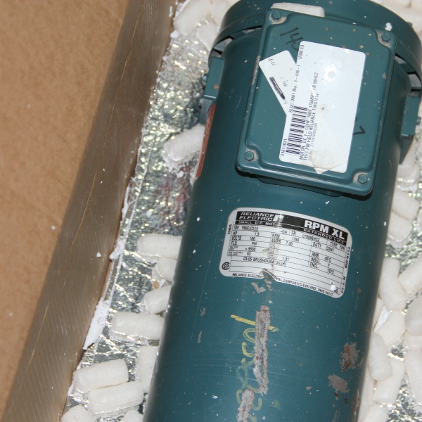
Hard-Numbers: Technical Specifications
- Horsepower: 1.5 HP (Continuous Duty)
- Voltage: 180V DC
- Full Load Current: 7.0 Amps
- Base Speed: 1750 RPM
- NEMA Frame: 56HC
- Enclosure: TEFC (Totally Enclosed Fan Cooled)
- Output Shaft Diameter: 7/8 inches
- Service Factor: 1.15 (Standard)
- Insulation Class: Class F (Industrial Standard)
- Duty Rating: Continuous
- Country of Origin: USA
- Mounting: Rigid base with standard 56HC foot pattern

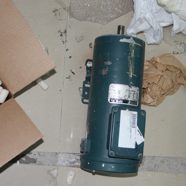
RELIANCE ELECTRIC T56S1014A
The Real-World Problem It Solves
You need a compact, workhorse DC motor for applications where AC power isn’t available or where precise speed control via armature voltage is required. The T56S1014A delivers 1.5HP in a NEMA 56HC footprint—small enough to fit tight machinery spaces but powerful enough for material handling, packaging equipment, and small machine tools.
Where you’ll typically find it:
- DC drive systems in older metalworking machinery and extruders
- Material handling conveyors requiring speed control
- Packaging lines where DC motor control is preferred
- Pump and fan applications with DC drive control
Bottom line: It’s a straightforward 56HC frame DC motor—no fancy encoders, no auxiliary devices—just reliable torque for general industrial drives running off 180V DC SCR controls.
Hardware Architecture & Under-the-Hood Logic
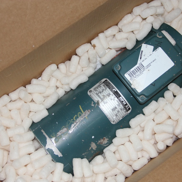
The T56S1014A is a standard permanent magnet DC motor with wound armature and field magnets. Power enters through a conduit box, runs through brushes to the rotating armature, and interacts with permanent field magnets to produce torque. The TEFC enclosure houses an internal fan that circulates cooling air across the frame.
- 180V DC power feeds into the armature through conduit box terminals
- Carbon brushes ride on commutator bars, conducting current to rotating armature windings
- Current flowing through armature conductors interacts with permanent magnetic field from stator
- Electromagnetic force (Lorentz force) generates torque on armature shaft
- Armature rotates at speed proportional to applied armature voltage
- Internal fan attached to rotor shaft draws air through TEFC enclosure
- Cooling air flows over frame fins and windings, dissipating heat
- Ball bearings support shaft at both ends, maintaining rotor alignment
- Commutator segments reverse current direction in armature coils for continuous rotation
- 7/8″ shaft extends from drive end, keyed for coupling or pulley mounting
- Rigid base with standard 56HC mounting foot pattern bolts to machinery frame
- Sealed bearings and TEFC enclosure protect internals from dust, moisture, and contaminants
- Brushes wear slowly over time—replacement interval depends on load and duty cycle
- Class F insulation allows continuous operation at rated temperature without breakdown
- No separate field winding—permanent magnets provide constant flux for simple speed-torque relationship
RELIANCE ELECTRIC T56S1014A
Field Service Pitfalls: What Rookies Get Wrong
Overloading the Armature on Startup
Newbies see the nameplate amps and assume the motor can handle 7.0A anytime. They ramp up voltage too fast or apply full load before the motor reaches speed, causing the armature to draw locked-rotor current—way beyond nameplate rating—and burning commutator bars or armature windings.
Field Rule: DC motors need controlled current limiting during startup. Ensure your DC drive has current limit set to 150% of rated current (10.5A) and ramp time long enough for the motor to accelerate smoothly. Never apply full voltage to a stalled motor—the commutator won’t survive the sustained high-current arcing.
Incorrect Polarity on First Spin
DC motors spin in one direction with proper polarity. Newbies wire armature connections backward on the drive output, and the motor runs reverse on first power-up. They panic and start swapping wiring at the motor, risking ground faults or incorrect motor rotation.
Quick Fix: Check rotation direction on low-voltage jog before coupling to the load. If rotation is wrong, swap the armature leads AT THE DRIVE OUTPUT TERMINALS only. Never swap polarity at the motor conduit box—that’ll confuse the next guy and may violate your own wiring standards. Leave the motor wired for one direction; handle reversals at the drive.
Neglecting Brush Maintenance
Carbon brushes wear down. Newbies run these motors for years without checking, then wonder why they get excessive sparking, poor commutation, or sudden motor failure from brush spring contact loss.
Field Rule: Pull brush caps and inspect brush length quarterly. If brushes are worn below 1/4 inch, replace them with the manufacturer’s specified grade. While you’re in there, check brush holder springs for tension and the commutator surface for grooving or discoloration. Light commutator wear is normal—deep grooving means you’ve got a problem (bearing misalignment or overload).
Running Unbalanced Loads on 7/8″ Shaft
The 7/8″ shaft is strong but not indestructible. Newbies install misaligned pulleys, couplings, or chain sprockets, causing vibration that beats up the bearings and eventually cracks the shaft extension.
Quick Fix: Check shaft runout with a dial indicator when replacing belts or couplings. Align drive components to within 0.003 inch TIR (Total Indicator Reading). Never hammer on the shaft—use a shaft heater or proper puller for removal. Vibration eats bearings and causes catastrophic shaft failure at the worst possible time.
Ignoring Bearing Temperature on Continuous Duty
TEFC enclosures are rated for continuous duty, but that assumes ambient temperature stays below 40°C and bearings get adequate lubrication. Newbies install these motors in hot rooms or in confined spaces where airflow is restricted, then wonder why bearing life drops to months instead of years.
Field Rule: Measure bearing temperature with an IR gun after the motor has run at full load for at least 4 hours. If bearing housing exceeds 85°C, you’ve got a cooling problem—clean fins, check airflow, or consider external forced cooling. Hot bearings cook grease and seize up, taking the whole motor down.
Wrong Wire Gauge for 7.0A Armature Current
Newbies run undersized wire to the motor to save cost or fit smaller conduit. 14 AWG is too light for 7.0A continuous, especially if the motor is 200 feet from the drive. Voltage drop kills torque and causes the motor to overheat trying to deliver required power.
Field Rule: Calculate voltage drop based on conductor length and load current. For 7.0A continuous and typical industrial run lengths, use 12 AWG copper minimum—10 AWG if you’re running over 150 feet from the drive. Voltage drop at the motor terminals should stay within 5% of nameplate voltage at full load. Anything more and you’re asking for performance issues.
Forgetting Grounding on TEFC Motors
TEFC enclosures protect against ingress but don’t protect personnel from fault currents. Newbies leave the ground lug disconnected or rely on the conduit for grounding—a violation and a lethal shock hazard.
Field Rule: Verify the green grounding screw in the conduit box has a solid, clean connection to plant ground. Test ground continuity with a megger or low-resistance ohmmeter. Never trust conduit alone for ground path—vibration loosens fittings and eventually you’re relying on a rusty thread. Grounding saves lives when armature insulation fails.
Commercial Availability & Pricing Note
Please note: The listed price is for reference only and is not binding. Final pricing and terms are subject to negotiation based on current market conditions and availability.


