
Description
Hard-Numbers: Technical Specifications
Note: Limited technical data available for S-D4008-E variant. Specifications below are based on available sources and S-D4008 series characteristics.
- Module Type: Analog I/O Card / Analog Control Module
- Communication Interface: RS-485
- Input Voltage (Logic Supply): 24V DC (typical)
- Current Consumption: 50 mA (typical)
- Communication Protocol: RS-485 (MODBUS RTU compatible on S-D4008 series)
- Operating Temperature: -40°C to +85°C (variant dependent)
- Storage Temperature: -40°C to +85°C
- Isolation Voltage: Channel isolation typical for PSC series (2500VDC nominal)
- Sampling Rate: Up to 1000 Hz on related S-D4008 variants
- Accuracy: ±0.1% (related S-D4008 series)
- Response Time: <1 ms (related S-D4008 series)
- Dimensions: 119mm × 91mm × 28mm (S-D4008 series reference)
- Weight: 0.2 kg (S-D4008 series reference)
- Mounting: DIN rail or rack mounting (system dependent)
- Protection: Built-in surge protection and isolation
- LED Indicators: Status indicators for power and communication activity
- Certifications: UL, cUL, CE (PSC series standard)

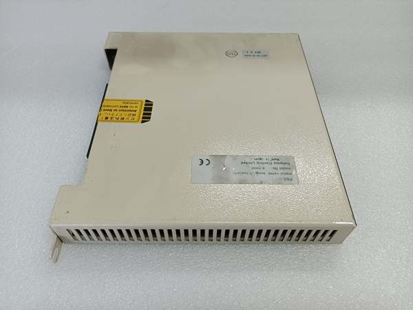
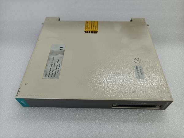
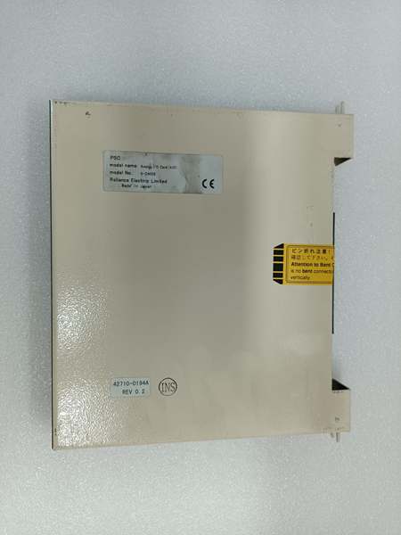
RELIANCE ELECTRIC S-D4008-E
The Real-World Problem It Solves
Precision analog signal handling is critical in servo control systems and process automation. The S-D4008-E provides high-accuracy analog input/output capabilities with RS-485 communication, enabling precise signal conversion between field devices and digital controllers while maintaining signal integrity in electrically noisy industrial environments.
Where you’ll typically find it:
- Reliance PSC3000/PSC4000/PSC5000/PSC7000 servo controller systems
- Automated motion control systems requiring analog sensor feedback
- Process control loops with analog actuators and transducers
- Legacy AutoMax DCS systems requiring analog expansion
- Industrial robotics and CNC machinery with analog interfaces
Bottom line: It delivers the analog precision your control loops demand with RS-485 communication for seamless integration—bridging the gap between legacy analog field devices and digital servo control architectures in harsh industrial environments.
Hardware Architecture & Under-the-Hood Logic
The S-D4008-E is an analog I/O module designed for Reliance PSC servo controller systems, providing high-precision analog signal conversion and communication with host controllers via RS-485 interface. It features multi-channel ADCs, DACs, signal conditioning circuits, and isolation to maintain signal accuracy in industrial environments.
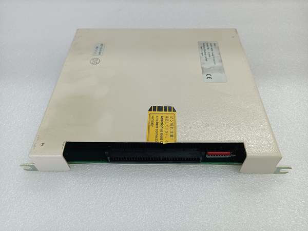
- Field device analog signals (voltage or current) enter through terminal block connectors
- Input protection circuits guard against overvoltage, reverse polarity, and ESD transients
- Signal conditioning circuits buffer and scale analog signals to ADC input range
- Multiplexed ADC channels sequentially sample all analog input channels at configured sampling rate
- Digital filtering algorithms remove noise and smooth signal variations
- Microcontroller processes digitized input values and stores in local data registers
- Host controller polls the S-D4008-E via RS-485 communication bus
- Microcontroller responds with requested input data values in communication frame format
- Host controller sends output commands via RS-485 to update analog outputs
- Microcontroller decodes commands and loads values into DAC registers
- DACs convert digital output values to analog voltage or current signals
- Output driver circuits amplify DAC outputs to required signal levels with drive capability
- Output protection circuits guard against short circuits and overload conditions
- Opto-isolation provides galvanic separation between field circuits and logic side (2500VDC typical)
- Terminal block connectors deliver analog signals to field actuators and sensors
- Internal voltage regulation provides stable logic supply from 24V system power
- Status LEDs indicate power, communication activity, and fault conditions
- Configuration memory holds communication parameters, scaling factors, and calibration data
RELIANCE ELECTRIC S-D4008-E
Field Service Pitfalls: What Rookies Get Wrong
Incorrect RS-485 Bus Wiring and TerminationRS-485 requires proper differential wiring and termination. Newbies wire lines incorrectly or omit termination resistors, causing communication errors, especially at higher baud rates or longer cable runs.
Field Rule: Install 120Ω termination resistors at both ends of the RS-485 bus. Use twisted-pair shielded cable with characteristic impedance of 120Ω. Maintain proper differential pair polarity (A+ to A+, B- to B-) throughout the network.
Grounding the Shield at Both EndsShielded cables are essential for noise immunity on RS-485 and analog signal lines. Newbies ground shields at both ends, creating ground loops that introduce more noise than the shield removes.
Quick Fix: Connect cable shields to the chassis ground terminal at the controller end only—leave shields floating at the field device end. Use drain wire pigtail connections to the shield terminal—never cut and terminate individual shield strands.
Mixing Voltage and Current Signal TypesThe S-D4008-E typically supports both voltage and current analog signals. Newbies connect 4-20mA transmitters to channels configured for voltage mode or vice versa, resulting in inaccurate readings or signal saturation.
Field Rule: Verify each channel’s signal type configuration in communication registers before field wiring. Use configuration software or write directly to signal type configuration registers. Label each cable with its signal type (V for voltage, I for current) at both ends to prevent cross-connection.
Incorrect Wiring of 4-20mA Current Loops4-20mA signals require series-wired current loops. Newbies wire current transmitters in parallel or fail to provide proper loop power, causing erratic readings or complete signal loss.
Field Rule: Verify current loop wiring is series-connected: transmitter positive → S-D4008-E input positive → S-D4008-E input negative → transmitter negative. Ensure the transmitter has adequate loop power (24V DC typical). Measure loop current with a multimeter in series to confirm 4-20mA range before connecting.
Exceeding Analog Output Drive CapabilityAnalog outputs have limited current drive capability. Newbies connect multiple loads in parallel or attempt to drive long cable runs with excessive capacitance, causing output voltage sag and inaccurate control.
Field Rule: Calculate total load current for each output channel. Use external signal amplifiers or isolators if driving multiple devices or long cable runs. Verify output accuracy under full load conditions during commissioning.
Ignoring RS-485 Address ConflictsEach device on the RS-485 bus must have a unique address. Newbies assign the same address to multiple modules, causing communication failures and bus contention.
Field Rule: Document all RS-485 slave addresses on your network diagram. Verify no address conflicts exist before commissioning. Use address switches (if available) or configure via software before installing the module.
Forgetting Calibration After InstallationFactory calibration may drift during shipping or installation. Newbies assume the module is calibrated out-of-the-box, leading to systematic measurement errors in critical control loops.
Field Rule: Perform input calibration using a precision voltage/current source before commissioning. Verify 4-20mA inputs read exactly 4mA at zero and 20mA at span. For outputs, verify exact voltage or current output at multiple setpoints (25%, 50%, 75%, 100%). Document calibration values.
Overloading Input Voltage RangeAnalog inputs have specified voltage ranges (typically 0-10V or ±10V). Newbies apply higher voltages from incompatible sensors, damaging input circuits permanently.
Quick Fix: Verify all sensor output voltages are within the S-D4008-E input range before connection. Use voltage dividers or signal conditioners for higher voltage sensors. Check sensor specifications carefully—some outputs 0-5V, others 0-10V, some are differential.
Not Using Proper Signal IsolationDifferent field devices may have different ground potentials. Newbies connect devices with different ground references directly to the S-D4008-E, causing ground loop errors and measurement offset.
Field Rule: Use isolated analog signal conditioners for devices with uncertain or different ground references. Verify isolation ratings match your application voltage levels. Consider using signal isolators even when not strictly necessary—they provide protection against unexpected ground differentials.
Please note: The listed price is for reference only and is not binding. Final pricing and terms are subject to negotiation based on current market conditions and availability.


