
Description
Hard-Numbers: Technical Specifications
- Analog Input Channels: 8 channels
- Analog Output Channels: 8 channels
- Input Signal Range: 0-10V DC or 4-20mA current loop
- Output Signal Range: 0-10V DC or 4-20mA current loop (±10V on some variants)
- Signal Types: Voltage and Current
- Sampling Rate: 100 Hz
- Communication Interface: RS-485
- Communication Protocol: MODBUS RTU
- Input Voltage (Logic Supply): DC 5V or DC 24V (variant dependent)
- Power Consumption: Max 12W (≤1W on some variants)
- Operating Temperature: -20°C to +60°C (extended to -40°C to +85°C on some variants)
- Storage Temperature: -40°C to +85°C
- Dimensions: 142mm × 95mm (170mm × 100mm × 25mm on some variants)
- Weight: 0.3 kg
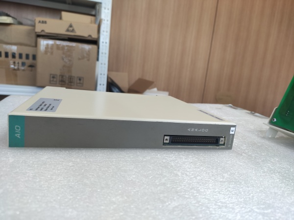
- Connectors: DB9 Male (Input), DB9 Female (Output)
- Resolution: 16-bit (from related S-D4008 base model reference)
- Isolation: Galvanic isolation between field circuits and logic (industry standard for PSC series)

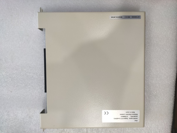
RELIANCE S-D4008-A
The Real-World Problem It Solves
Industrial process control requires precise analog signal handling for continuous variable monitoring and control. The S-D4008-A provides 8-input/8-output analog channels with MODBUS RTU communication, enabling accurate process variable measurement (temperature, pressure, flow, level) and control valve positioning without sacrificing signal integrity in electrically noisy environments.
Where you’ll typically find it:
- Process control systems (temperature, pressure, flow rate regulation)
- Manufacturing process automation with analog sensor arrays
- Building automation systems (HVAC control loops)
- Water treatment plants with chemical feed control
- Food and beverage processing lines requiring precise analog control
Bottom line: It delivers the analog precision your process loops demand with MODBUS RTU communication for seamless integration into modern distributed control systems—bridging the gap between legacy analog field devices and digital control architectures.
Hardware Architecture & Under-the-Hood Logic
The S-D4008-A is an analog I/O module designed for Reliance PSC (Programmable Servo Controller) systems, providing high-precision analog signal conversion and communication with host controllers via MODBUS RTU protocol over RS-485. It features multi-channel ADCs, DACs, signal conditioning circuits, and robust isolation to maintain signal accuracy in industrial environments.
- Field device signals (0-10V or 4-20mA) enter through DB9 input connectors
- Input protection circuits guard against overvoltage, reverse polarity, and ESD transients
- Signal conditioning circuits buffer and scale analog signals to ADC input range
- Multiplexed 16-bit ADC channels sequentially sample all 8 analog input channels at 100Hz rate
- Digital filtering algorithms remove noise and smooth signal variations
- Microcontroller processes digitized input values and stores in local data registers
- Host controller polls the S-D4008-A via MODBUS RTU over RS-485 bus
- Microcontroller responds with requested input data values in MODBUS frame format
- Host controller sends output commands via MODBUS RTU to update analog outputs
- Microcontroller decodes MODBUS commands and loads values into DAC registers
- 16-bit DACs convert digital output values to analog voltage or current signals
- Output driver circuits amplify DAC outputs to 0-10V or 4-20mA range with required drive capability
- Output protection circuits guard against short circuits and overload conditions
- Opto-isolation or transformer isolation provides galvanic separation between field circuits and logic side (2500V typical for PSC series)
- DB9 output connectors deliver analog signals to field actuators and control devices
- Internal voltage regulation provides stable 5V logic supply from 24V system power
- Status LEDs indicate communication activity and fault conditions
- Configuration memory holds communication parameters, scaling factors, and calibration data
RELIANCE S-D4008-A
Field Service Pitfalls: What Rookies Get Wrong
Mixing Voltage and Current Signal Ranges Without ConfigurationThe S-D4008-A supports both 0-10V and 4-20mA signals on each channel. Newbies connect 4-20mA transmitters to channels configured for voltage mode, resulting in inaccurate readings or signal saturation.
Field Rule: Verify each channel’s signal type configuration in MODBUS registers before field wiring. Use configuration software or write directly to signal type configuration registers. Label each cable with its signal type (V for voltage, I for current) at both ends to prevent cross-connection during maintenance.
Improper RS-485 Bus TerminationMODBUS RTU over RS-485 requires proper termination at both ends of the bus. Newbies leave termination resistors disabled, causing signal reflections and communication errors, especially at higher baud rates or longer cable runs.
Quick Fix: Install 120Ω termination resistors at both the first and last devices on the RS-485 bus. Use shielded twisted-pair cable with characteristic impedance of 120Ω. Ground the shield at the controller end only—never ground both ends to avoid ground loops.
Incorrect Wiring of 4-20mA Current Loops4-20mA signals require series-wired current loops. Newbies wire current transmitters in parallel with voltage signals or fail to provide proper loop power, causing erratic readings or complete signal loss.
Field Rule: Verify current loop wiring is series-connected: transmitter positive → S-D4008-A input positive → S-D4008-A input negative → transmitter negative. Ensure the transmitter has adequate loop power (24V DC typical). Measure loop current with a multimeter in series to confirm 4-20mA range before connecting to the module.
Ground Loops from Multiple Analog Signal SourcesMultiple grounded analog devices connected to the S-D4008-A create ground loops, causing measurement offset, drifting readings, and noise—especially in facilities with different ground potentials between equipment areas.
Quick Fix: Use isolated analog transmitters wherever possible. For non-isolated sensors, connect the signal negative (return) wire only at the S-D4008-A end—leave the sensor floating or reference it to its local ground. Signal isolators may be required for difficult ground loop situations.
Ignoring MODBUS Address ConflictsEach device on the RS-485 bus must have a unique MODBUS slave address. Newbies assign the same address to multiple S-D4008-A cards, causing communication failures and bus contention.
Field Rule: Document all MODBUS slave addresses on your RS-485 network diagram. Verify no address conflicts exist before commissioning. Use address switches (if available) or configure via software before installing the module. Consider reserving address ranges for specific equipment types (e.g., addresses 1-10 for analog I/O, 11-20 for drives).
Overloading Analog Output Current CapabilityAnalog outputs have limited current drive capability (typically 5-20mA). Newbies connect multiple control valve positioners in parallel to a single output, or attempt to drive long cable runs with excessive capacitance, causing output voltage sag and inaccurate control.
Field Rule: Calculate total load current for each output channel. Use external signal amplifiers or isolators if driving multiple devices or long cable runs. Verify output accuracy under full load conditions during commissioning.
Not Calibrating After InstallationFactory calibration may drift during shipping or installation. Newbies assume the module is calibrated out-of-the-box, leading to systematic measurement errors in critical process loops.
Field Rule: Perform input calibration using a precision voltage/current source before commissioning. Verify 4-20mA inputs read exactly 4mA at zero and 20mA at span. For outputs, verify exact voltage or current output at multiple setpoints (25%, 50%, 75%, 100%). Document calibration values and adjust offset/span registers as needed.
Improper Shield Grounding on Analog CablesShielded cables are required for noise immunity, but improper grounding defeats the purpose. Newbies ground shields at both ends, creating ground loops that introduce more noise than the shield removes.
Field Rule: Connect cable shields to the S-D4008-A chassis ground terminal only—leave shields floating at the field device end. Use drain wire pigtail connections to the shield terminal—never cut the shield braid and attempt to terminate individual strands. Maintain separation between analog cable shields and power cable grounds.
Please note: The listed price is for reference only and is not binding. Final pricing and terms are subject to negotiation based on current market conditions and availability.


