
Description
Hard-Numbers: Technical Specifications
- Module Type: Digital Output Module (4-Channel)
- Number of Channels: 4 digital output channels
- Output Current: 2A per channel
- Output Voltage: 24V DC
- Response Time: 1μs
- Communication Protocol: Modbus RTU
- Power Consumption: 2W
- Operating Temperature: -20°C to +70°C
- Dimensions: 115mm x 82mm x 25mm
- Weight: 0.2 kg
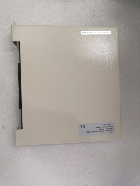
- Material: Plastic enclosure
- Mounting: DIN rail mountable
- Isolation: 500V AC isolation between output channels and system (for related S-D4007 variants)
- Contact Form: Form A Normally Open (NO) – relay outputs on related variants

RELIANCE S-D4007-K
The Real-World Problem It Solves
Industrial control racks need compact, reliable digital output modules to drive field devices without sacrificing cabinet space or response time. The S-D4007-K provides four isolated 2A outputs in a single 115mm-wide package, delivering fast 1μs switching response through Modbus RTU communication to AutoMax processors.
Where you’ll typically find it:
- AutoMax distributed control system racks in pulp and paper mills
- Manufacturing assembly lines controlling solenoid valves and indicator stacks
- Process industry panels driving alarm horns and control relays
- Legacy Reliance Electric/BCD retrofit installations requiring S-Series I/O expansion
Bottom line: It’s a space-saving digital output workhorse for AutoMax DCS racks—providing reliable field device control with rapid response when cabinet real estate is tight.
Hardware Architecture & Under-the-Hood Logic
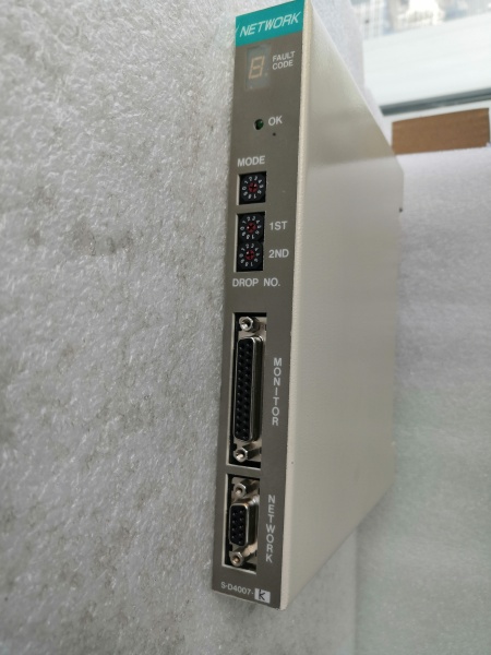
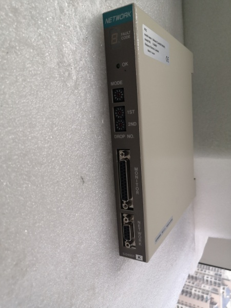
The S-D4007-K is a 4-channel digital output module designed as a Modbus RTU slave device for Reliance S-Series programmable logic controllers. It contains no onboard microprocessor—output control logic resides in the host AutoMax processor, with the module handling power switching and isolation.
- AutoMax processor sends Modbus RTU commands to S-D4007-K via backplane communication bus
- Module’s Modbus interface receives digital output state commands (ON/OFF) for each of 4 channels
- Output drivers (solid-state or relay depending on specific variant) switch the 24V DC output lines
- Each output channel delivers up to 2A current to connected field devices
- Optical isolation separates the logic side from the output side for noise immunity
- Output protection circuitry prevents damage from short circuits or overcurrent conditions
- Status feedback signals report output state and fault conditions back to the AutoMax processor
- Internal power regulation derives 24V from backplane for internal circuitry
- DIN rail mounting clips secure the module in standard control cabinets
- Faceplate LEDs indicate power status and per-channel output state for quick visual diagnostics
- Removable terminal block facilitates field wiring without removing the entire module
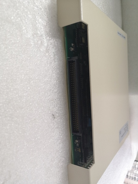
- Backplane connector carries both power and communication signals to/from the AutoMax rack
- Output filtering suppresses electrical noise generated during switching transients
- Watchdog timer monitors module health and resets if communication is lost
- Module address configuration via DIP switches or software configuration determines Modbus node ID
RELIANCE S-D4007-K
Field Service Pitfalls: What Rookies Get Wrong
Overloading 2A Per Channel Rating
Each output channel is rated for 2A continuous current. Newbies daisy-chain multiple devices to a single output or calculate total rack load incorrectly, exceeding the per-channel limit and causing output failure or module damage.
Field Rule: Calculate load current for each individual output channel before wiring. If a device requires more than 2A, use an external contactor or relay driven by the S-D4007-K output. Never assume that “total module rating” applies to any single channel. Each channel is individually protected and limited.
Ignoring Backplane Communication Requirements
The S-D4007-K requires proper Modbus RTU addressing and compatible AutoMax firmware. Newbies install the module without configuring the node address, causing communication conflicts or the module being ignored by the processor.
Quick Fix: Before installing, verify that no other device in the AutoMax rack uses the same Modbus address. Configure the module’s address via DIP switches or through AutoMax Programming Executive software. After installation, use the software’s node detection feature to confirm the module is visible on the network.
Mixing 24V DC and AC Field Devices
The module outputs 24V DC only. Newbies connect AC coils or devices requiring higher voltages directly to the outputs, resulting in no operation or immediate output driver destruction.
Field Rule: Verify that all field devices connected to S-D4007-K outputs are rated for 24V DC operation. For AC loads, use appropriately rated interposing relays with 24V DC coils. Check coil voltage and contact ratings of any external relays—never exceed the 2A output capacity of the module.
Improper Wiring of Terminal Blocks
The S-D4007-K uses removable terminal blocks for field connections. Newbies overtighten terminals, causing wire breakage or screw damage, or undertighten, leading to loose connections and intermittent operation.
Field Rule: Use a torque screwdriver set to the manufacturer’s specification (typically 0.5-0.6 Nm for these terminal blocks). After wiring, perform a gentle pull-test on each wire to confirm secure connection. Label wires corresponding to channel numbers—the faceplate LED indicators won’t help if the wire is in the wrong terminal.
Neglecting Output Protection for Inductive Loads
Solenoids and relays generate voltage spikes when de-energized. Newbies connect these inductive loads directly without protection, causing the output drivers to degrade over time or fail prematurely.
Quick Fix: Install flyback diodes across inductive coil terminals (cathode to positive, anode to negative). For DC solenoids, a diode rated for at least the load current with sufficient voltage rating (typically 1.5-2x supply voltage) protects the output. This is cheap insurance that extends module life significantly.
Mixing Source and Sink Wiring Configurations
The S-D4007-K outputs typically source current (supply positive). Newbies wire field devices expecting sink configuration, resulting in no operation.
Field Rule: Verify your field device’s input type before wiring. If the device requires sinking (provides common ground), you may need an external relay to invert the signal or reconfigure the device if possible. AutoMax configurations can often be set for source or sink operation—match the module configuration to your field wiring scheme.
Operating Beyond Temperature Range
The module is rated for -20°C to +70°C. Newbies install modules in enclosures without adequate ventilation or near heat-generating components, causing intermittent operation or thermal shutdown.
Field Rule: Monitor cabinet temperature, especially in outdoor or unconditioned environments. Ensure adequate airflow around the module. If ambient temperatures approach +60°C, consider adding cabinet ventilation or derating the output loads. The 2A per channel rating assumes proper operating temperature.
Failing to Address Ground Loops
Improper grounding causes erratic operation and communication errors. Newbies run shielded cable grounds to multiple points, creating ground loops that corrupt Modbus communication.
Quick Fix: Ground the shield at one point only—typically at the AutoMax rack end. Use star grounding topology for field device commons. Verify that the 0V reference of the 24V DC supply is properly bonded to the cabinet ground at a single point. Ground loops are a silent killer of reliable Modbus communication.
Forgetting Backup Module Configuration
When replacing a failed S-D4007-K, newbies swap the module but forget to transfer the Modbus address configuration, causing communication failure or incorrect output mapping.
Field Rule: Before removing a failed module, document its Modbus node address and any critical configuration parameters. When installing the replacement, configure the new module with the same address and settings. This prevents the need to reconfigure the entire AutoMax program or hunt down why certain outputs aren’t responding.
Daisy-Chaining Field Power Supplies
The S-D4007-K derives 24V from the backplane. Newbies attempt to power additional field devices from the same 24V supply that feeds the module, exceeding the backplane’s current capacity.
Field Rule: Calculate total current draw from the backplane power supply. The S-D4007-K consumes 2W internally, plus the 2A per channel output current must be supplied by the AutoMax rack power supply. If driving high-current loads, verify that the rack power supply has sufficient capacity. Never tap field device power from module terminals—power field devices from separate properly sized supplies.
Commercial Availability & Pricing Note
Please note: The listed price is for reference only and is not binding. Final pricing and terms are subject to negotiation based on current market conditions and availability.


