
Description
Hard-Numbers: Technical Specifications
- I/O Point Count: 16 input/output points (configurable)
- I/O Configuration: Digital Input/Output
- Nominal Supply Voltage: 24VDC
- Input Voltage Range: 10 to 30VDC
- Output Voltage Range: 0 to 24VDC
- Output Current per Point: 2A
- Isolation Voltage: 2500VDC (between field circuits and logic)
- Operating Temperature: -25°C to +70°C
- Storage Temperature: -40°C to +85°C
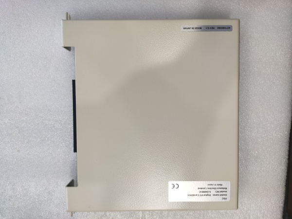
- Dimensions: 120mm × 60mm × 22mm
- Weight: 200 grams (0.2 kg)
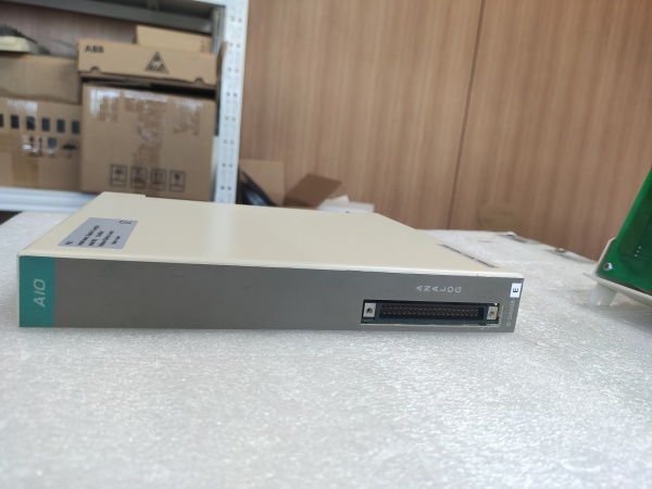
- Status Indication: LED indicators for I/O points and fuse status
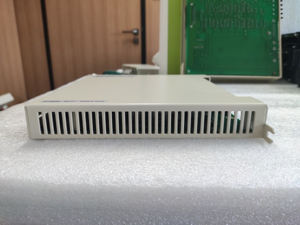
- Installation Method: Rack-mount or DIN rail installation
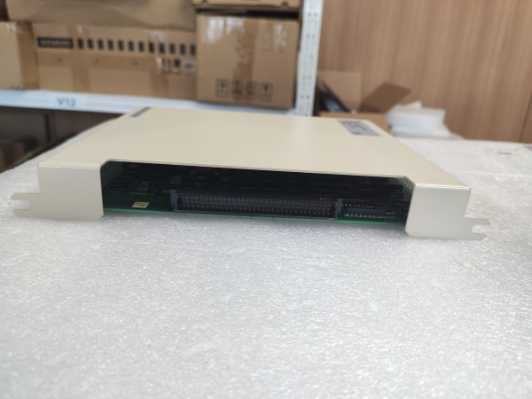
- Communication: Backplane data bus integration with host controller

S-D4008-A
The Real-World Problem It Solves
Industrial I/O systems need robust isolation between harsh field environments and sensitive controller logic. The S-D4006-F provides 2500VDC galvanic isolation across 16 channels, protecting control systems from ground loops, induced surges, and noisy field devices while delivering 2A output current for driving actuators directly.
Where you’ll typically find it:
- Conveyor systems and material handling equipment
- Packaging machinery with sensor arrays and solenoid actuators
- Robotics workcells with digital I/O requirements
- Automotive manufacturing assembly lines
- Process control systems interfacing with discrete field devices
Bottom line: It delivers industrial-grade isolation and 2A output capacity in a compact form factor—proving you don’t need massive I/O racks to get serious protection against the electrical nightmares of real-world field environments.
Hardware Architecture & Under-the-Hood Logic
The S-D4006-F is a digital I/O module designed for Reliance automation platforms, providing galvanically isolated input sensing and output switching with robust overcurrent protection. It integrates opto-couplers, current limiting circuits, and blown-fuse detection to maintain signal integrity and protect both field devices and controller logic.
- Field device signals (10-30VDC input range) enter through input terminal blocks
- Current limiting resistors (approx. 2.4kΩ) protect input opto-couplers from excessive current
- Opto-couplers provide 2500VDC galvanic isolation between field circuits and internal logic
- Input filter circuits (approx. 30Hz cutoff) suppress contact bounce and remove external noise
- Internal microcontroller scans all 16 input channels at configured scan rate
- Digital input states are buffered and transmitted via backplane data bus to host controller
- Controller commands output states via backplane bus to the module
- Output microcontroller receives commands and drives output switching transistors
- Output drivers energize or de-energize field devices (solenoids, relays, indicator lamps)
- Current limiting circuits on each output channel protect against short circuits
- Fuse protection on output circuits clears hard faults (blown fuses trigger red LED indicator)
- Blown fuse detection circuit monitors each channel and illuminates front-panel fault LED
- Status LEDs display real-time continuity state for all 16 I/O points
- Input/output changeover switch allows viewing either input or output status on the 16-point indicator array
- Internal voltage regulation provides stable logic voltages from 24VDC supply
S-D4008-A-F
Field Service Pitfalls: What Rookies Get Wrong
Exceeding Input Voltage RangeThe S-D4006-F accepts 10-30VDC on input channels. Newbies wire 120VAC proximity switches or 48VDC field devices directly, instantly destroying opto-couplers and input circuitry.
Field Rule: Verify all field device signal voltages are within the 10-30VDC range before connection. For higher voltage devices (24VAC, 120VAC, 48VDC), use interposing relays or signal converters—never exceed the specified input voltage range.
Overloading Output Channels Beyond 2A RatingEach output point can sink 2A maximum. Newbies connect multiple solenoids in parallel to a single output or drive high-current loads directly, causing output transistor failure and blown module fuses.
Quick Fix: Calculate total load current for each output channel (sum of all parallel devices). Use external interposing relays for loads exceeding 2A or for driving multiple actuators from one logic output. Let the S-D4006-F drive the relay coil (typically 100-200mA) and let the relay contacts handle the load current.
Ignoring Blown Fuse LED IndicationThe front-panel red LED illuminates when any output fuse blows. Newbies chase controller software faults while a blown fuse has been signaling hardware protection, wasting hours troubleshooting non-existent logic problems.
Field Rule: Include fuse LED status in your initial fault diagnosis workflow. A lit red LED means immediate physical fuse verification—check the fuse holder, measure fuse continuity, and identify the shorted field device before resetting any controller fault logic.
Forgetting Both Channels Need Power SupplyOutput channels are grouped in pairs with shared power supply connections. Newbies power only one channel in a pair, causing the other channel to report as disconnected or failed, even when unused.
Quick Fix: Ensure both channels in each pair have their power supply connections made, even if you’re only using one channel. The module’s blown fuse detection circuit expects both channels to be powered to prevent false fault indications.
Mixing Signal and Power Wiring on 40-Pin ConnectorsThe S-D4006-F uses 40-pin connectors for field wiring. Newbies don’t follow the pinout precisely, cross-wiring signals and power, or confusing input and output connector assignments during installation.
Field Rule: Always verify connector pinout against the manual before terminating cables. Use the manufacturer-specified connector assemblies or match pin-for-pin. Label both ends of your cable assemblies with module designation and connector type to prevent cross-connection during maintenance.
Neglecting Grounding for Noise ImmunityDespite 2500VDC isolation, poor grounding practices still introduce noise. Newbies run unshielded I/O wiring adjacent to VFD output cables or motor feeders, causing false triggering and erratic counts.
Quick Fix: Use shielded twisted-pair cable for all I/O wiring runs over 3 meters. Ground the shield drain wire at the cabinet end only—never ground both ends to avoid ground loops. Maintain minimum 6-inch separation in cable trays between I/O wiring and power cables carrying more than 5A.
Hot-Swapping Without Verifying CompatibilitySome Reliance platforms support hot-swap, but not all configurations are compatible. Newbies pull and replace S-D4006-F modules while the rack is energized without confirming hot-swap capability, risking backplane damage and system crashes.
Field Rule: Verify your specific controller firmware and backplane revision support hot-swap operations. When in doubt, power down the rack and follow proper lockout/tagout procedures. If hot-swap is supported, use the module ejector mechanism—never yank modules by their cable harnesses.
Please note: The listed price is for reference only and is not binding. Final pricing and terms are subject to negotiation based on current market conditions and availability.


