
Description
Hard-Numbers: Technical Specifications
- I/O Point Count: 32 points (configurable as inputs or outputs)
- I/O Configuration: Digital Input/Output (selectable)
- Switch Type: Form A Normally Open
- Maximum Switching Voltage: 200 VDC
- Maximum Switching Power: 10 watts
- Operating Voltage: 220 VAC (system)
- Input Voltage Range: 115/230 VAC
- Phase Configuration: Single-phase
- Line Frequency: 50/60 Hz
- Rated Power: 1.0/2.0 HP
- Memory Capacity: 512 KB (for configuration and data storage)
- Communication Interfaces: Ethernet, RS-485
- Dimensions: 130mm × 102mm × 40mm (13cm × 10.2cm × 4cm)
- Weight: 0.35 kg (350 grams)
- Enclosure Rating: NEMA 12K (indoor industrial)
- Operating Temperature: -10°C to +60°C
- Storage Temperature: -40°C to +85°C
- Certifications: CE, UL

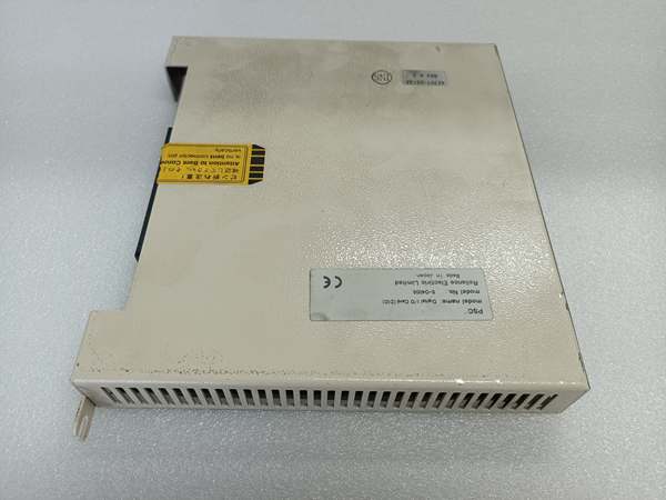
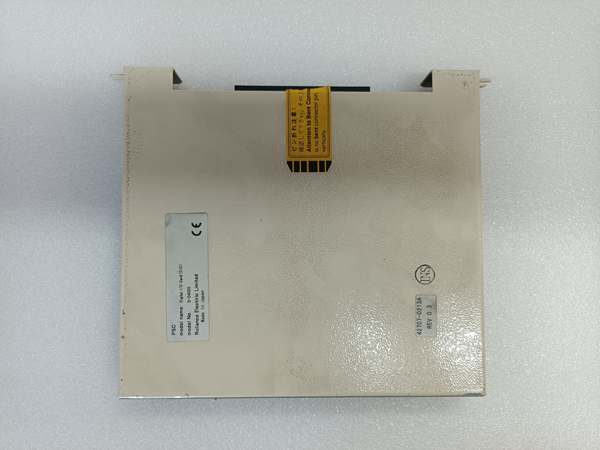
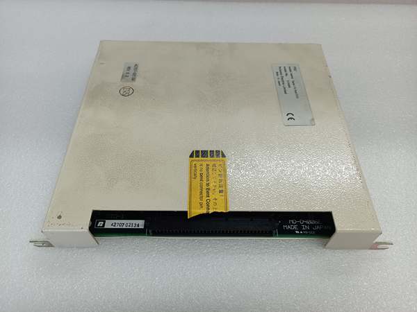
Reliance S-D4006-D
The Real-World Problem It Solves
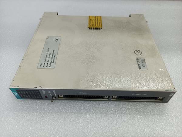
Control systems need a reliable interface between logic controllers and the messy world of field devices—limit switches that bounce, proximity sensors that drift, and relays that weld contacts. The S-D4006-D provides 32 protected digital channels with visual fuse status, giving maintenance crews instant diagnostic visibility without opening the cabinet or wrestling with multimeter probes.
Where you’ll typically find it:
- Production line control systems monitoring conveyor positions and sensor arrays
- Packaging machinery controlling pneumatic actuators and optical sensors
- Manufacturing automation systems managing discrete safety interlocks and status indicators
- Process control applications interfacing with valve position switches and motor starters
- Building automation systems controlling lighting, HVAC, and security relays
Bottom line: It’s a workhorse 32-point digital interface that keeps field signal integrity intact while making fuse failures immediately visible—no more hunting for blown I/O protection with a flashlight and multimeter during emergency shutdowns.
Hardware Architecture & Under-the-Hood Logic
The S-D4006-D is a rack-mounted digital I/O module designed for Reliance automation platforms, converting field device discrete signals into logic-level data for controller processing and executing controller commands to drive field actuators. It integrates opto-isolation, overcurrent protection, and status indication in a compact form factor supporting high-density I/O deployment.
- Field device signals (24VDC or 120VAC typical) enter through input terminals
- Input opto-isolators provide galvanic separation between field circuits and internal logic
- Input conditioning circuits filter contact bounce and normalize signal thresholds
- Internal microcontroller scans all 32 input channels at configured scan rate
- Digital input states are buffered and transmitted via backplane bus to host controller
- Controller outputs digital commands via backplane bus to the module
- Output microcontroller receives commands and drives output driver transistors
- Output drivers energize or de-energize field devices (relays, solenoids, indicator lights)
- Current limiting circuits protect each output channel against short circuits and overloads
- Fuse protection on output circuits clears hard faults and prevents module damage
- Fuse status monitoring circuit detects blown fuses and illuminates front-panel indicator
- LED indicators display real-time I/O status and fault conditions for rapid diagnostics
- Communication processor handles data exchange via Ethernet and RS-485 interfaces
- Configuration memory (512KB) stores I/O mapping, scan rates, and operational parameters
- Power supply regulation provides stable internal logic voltages from system power source
Reliance S-D4006-D
Field Service Pitfalls: What Rookies Get Wrong
Mixing AC and DC on Unprotected InputsThe S-D4006-D supports both AC and DC field devices, but newbies don’t verify input isolation ratings or mix 24VDC proximity sensors with 120VAC limit switches on adjacent channels. This creates ground loops, noise issues, or input circuit damage when isolation limits are exceeded.
Field Rule: Verify the input type configuration matches your field device voltage levels. Keep AC and DC field circuits separated whenever possible. Use interposing relays if you need to mix AC and DC signals—never wire them directly to the same I/O module without confirming isolation specifications.
Overlooking Contact Bounce on Mechanical InputsLimit switches and mechanical sensors generate contact bounce during actuation. Newbies treat the bouncing signal as multiple rapid state changes, causing controller logic to execute unintended cycles or count falsely.
Quick Fix: Enable input filtering in your controller program or use the S-D4006-D built-in debounce configuration if available. For mechanical switches, implement a minimum on-time filter of 10-50ms to debounce the signal before logic processes the state change.
Ignoring Fuse Indicator Status During FaultsThe front-panel fuse indicator provides immediate blown-fault visibility. Newbies chase controller faults for hours while a blown output fuse has been staring them in the face, causing uncommanded shutdowns and intermittent operation.
Field Rule: Include fuse indicator status in your initial fault diagnosis checklist. A lit fuse indicator means immediate physical verification of the fuse holder—don’t waste time troubleshooting software logic when hardware protection has already activated.
Exceeding Maximum Switching Power on OutputsEach output channel is rated for maximum 10 watts at 200 VDC. Newbies drive inductive loads directly from I/O outputs, ignoring the power rating and causing output transistor failure or contact welding in relay-interfaced modules.
Quick Fix: Calculate load power (P = V × I) before connecting to output channels. For loads exceeding 10 watts or high-current inductive devices (solenoids, motor starters), use external interposing relays. Let the relay contacts handle the load current and use the S-D4006-D output to drive the relay coil.
Poor Terminal Block Torqueing PracticesThe S-D4006-D uses screw terminal connections for field wiring. Newbies either over-torque terminals, stripping screws and damaging wire strands, or under-torque connections, causing intermittent contact faults that appear as random I/O errors.
Field Rule: Use a properly calibrated torque screwdriver. Follow manufacturer torque specifications—typically 0.5-0.6 Nm for terminal block screws. Periodically re-torque terminals during scheduled maintenance, especially in vibration-prone environments where thermal cycling loosens connections over time.
Neglecting Grounding and Shielding on Long Cable RunsLong sensor and actuator cables act as antennas for EMI. Newbies run unshielded I/O wiring adjacent to high-power motor cables, causing false triggering, erratic counts, or output state drift.
Quick Fix: Use shielded twisted-pair cable for all digital I/O wiring runs longer than 3 meters. Ground the shield drain wire at the cabinet end only—never ground both ends to avoid ground loops. Maintain minimum 6-inch separation between I/O wiring and power cables in cable trays.
Hot-Swapping Without Verifying CompatibilityThe S-D4006-D may support hot-swapping in certain configurations. Newbies pull and replace modules while the system is energized without confirming hot-swap capability, causing backplane damage or system crashes.
Field Rule: Verify hot-swap capability in your specific system configuration before attempting live replacement. If hot-swap is supported, use the module ejector mechanism properly—never yank modules by their cable harnesses. When in doubt, power down the rack and follow proper lockout/tagout procedures.
Please note: The listed price is for reference only and is not binding. Final pricing and terms are subject to negotiation based on current market conditions and availability.


