
Description
Hard-Numbers: Technical Specifications
- Part Number: 27713
- Board Type: Base Board PCB
- Processor/Controller: PISC-60 (Programmable Integrated System Controller)
- Compatible Drive Series: Reliance GP-2000 AC VS Drives
- Related Boards in Series:
- MD-B0003E (Fiber-Optic Communication Module) – $783.00
- MD-B3006C (Remote Meter Interface Board) – $151.00
- Manufacturer: Reliance Electric (later Baldor Reliance / ABB)
- Country of Origin: USA
- Operating Environment: Industrial drive cabinets, typically NEMA 1 or NEMA 12 enclosures
- Mounting: Plug-in card rack system within drive cabinet
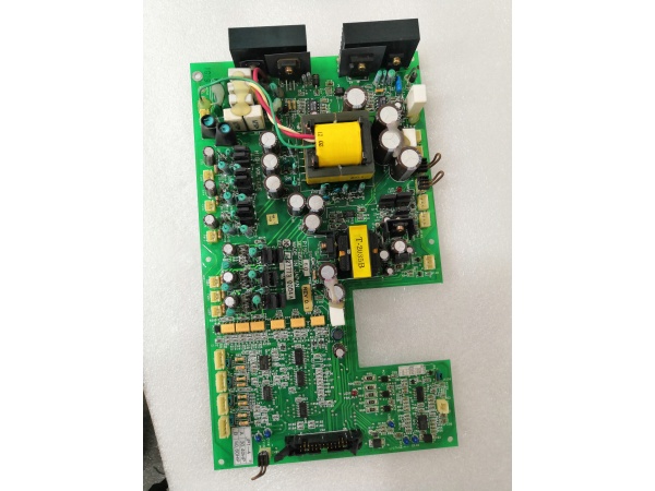
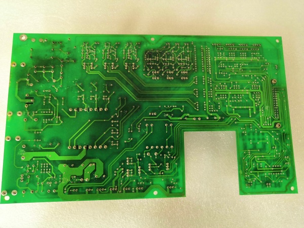
MD-B6027C
The Real-World Problem It Solves
The MD-B6027C serves as the central nervous system for Reliance GP-2000 AC drives. It coordinates power stage control, user interface communication, feedback processing, and protection logic—all from a single board that field techs can swap out in minutes. Instead of debugging individual components on failed drives, you replace the base board and get production back online.
Where you’ll typically find it:
- GP-2000 series AC variable frequency drives in manufacturing plants
- Pump and fan applications requiring precise speed control
- Conveyor systems with adjustable motor control
- Compressor and blower drive systems
- Retrofits where older analog drives were replaced with GP-2000 digital control
Bottom line: It’s the brain that keeps GP-2000 drives running—manageable replacement for catastrophic board failures without replacing the entire drive unit.
Hardware Architecture & Under-the-Hood Logic
The MD-B6027C is a multi-layer PCB designed as the central processing board within the GP-2000 drive architecture. It interfaces with power modules, operator interfaces, and communication networks through standardized connectors.
- PISC-60 Processor – Main programmable controller executing drive algorithms, motor control logic, and protection functions
- Power Stage Interface – Connects to IGBT modules and gate drive circuits via shielded cables
- Feedback Input Channels – Receives encoder, tachometer, or sensorless feedback signals
- Analog I/O Section – Handles 4-20mA, 0-10V speed reference and feedback signals
- Digital I/O Circuitry – Processes start/终止, forward/reverse, fault, and status inputs
- Communication Interfaces – Supports optional communication cards (Profibus, DeviceNet, Modbus, etc.)
- Operator Panel Connector – Links to local keypads and display modules (e.g., MD-B3006C Remote Meter Interface)
- LED Status Indicators – Power, run, fault, and communication status LEDs for diagnostics
- DIN Rail / Card Rack Mounting – Slides into drive cabinet rack system with secure locking mechanism
- Isolation Circuits – Opto-isolation on digital inputs/outputs to protect logic from noise
- Power Supply Regulation – On-board DC/DC converters generating ±15V, +5V, and +3.3V for internal logic
- Non-Volatile Memory – Stores parameter settings, fault history, and configuration data
- Watchdog Timer – Monitors processor operation and triggers safe shutdown on fault detection
- Flash EPROM – Firmware storage allowing field updates without chip replacement
- Terminal Blocks – Screw terminals for direct wiring of I/O and power connections

MD-B6027C
Field Service Pitfalls: What Rookies Get Wrong
Failing to Backup Parameters Before Board Swap
Newbies pull the failed MD-B6027C and plug in a replacement without documenting drive parameters. The new board boots with factory defaults, and the motor runs wrong—or not at all. Production halts while they scramble to figure out torque curves, acceleration rates, and current limits.
Field Rule: Always document parameter settings via keypad menu or communication software before removing any board. Write down critical values: motor FLA, voltage, acceleration/deceleration times, current limits, and any customized protection settings. Take photos of parameter screens if available. Reliance drives retain settings in non-volatile memory, but board transfer doesn’t guarantee preservation—assume the new board is factory-fresh.
Ignoring Grounding Straps During Removal
Rookies rip boards out of card racks without noting or reconnecting grounding straps. These straps prevent ESD damage and ensure proper chassis ground reference. Missing ground straps cause erratic behavior, intermittent faults, or premature board failure from static discharge.
Quick Fix: Locate all grounding straps or wires connected to the MD-B6027C chassis or mounting bracket. Note their connection points and reattach them to the replacement board in the exact same locations. If a grounding strap looks loose or corroded, replace it—don’t assume it was optional.
Hot-Swapping Without Power Discharge
Some field techs think they can pull boards quickly without waiting for DC bus discharge. The GP-2000 drive stores lethal DC bus voltage in capacitors even after line power is removed. Touching live circuits or inserting boards with charged capacitors causes catastrophic board failure and serious injury.
Field Rule: Disconnect line power and wait at least 5 minutes before opening cabinet doors. Verify DC bus voltage has discharged below 50V using a multimeter on bus terminals. Only then should you approach card racks. Never assume capacitors are drained—always verify with meter before touching anything inside the drive.
Mismatching Firmware Versions
Newbies install replacement boards without checking firmware compatibility. If the new board has different firmware than the removed unit, parameter structures change, and stored values from the old board may not load correctly. Some firmware versions add parameters that older versions don’t recognize, causing fault codes on boot.
Quick Fix: Check firmware version on replacement board via keypad menu during power-up (usually under “System Info” or “Diagnostics” menu). If the version differs from your documented original, update firmware to match or note parameter mapping differences in your service log. Always keep firmware current across all drives in the same plant—mismatched firmware causes headaches during troubleshooting.
Overlooking Option Card Dependencies
The MD-B6027C base board works with option cards like the MD-B0003E Fiber-Optic Communication Module or MD-B3006C Remote Meter Interface. Rookies swap the base board but forget that option cards may need jumpers set or dip-switches configured differently for the new board revision.
Field Rule: Document all option card configurations and jumper settings before removal. Note which slots option cards occupy—different MD-B6027C revisions may assign different functionality to specific slots. After installing the new base board, verify option cards are recognized via keypad menu and communication links are functional before restoring motor power.
Neglecting LED Diagnostics After Installation
Experienced techs power up the drive and immediately start testing motor operation. Rookies ignore the LED status indicators on the replacement board, missing early warning signs of configuration errors or incompatible option cards.
Quick Fix: Spend 60 seconds observing LED behavior on the new MD-B6027C after power-up:
- Power LED should illuminate immediately
- Run LED stays off until drive is enabled
- Fault LED blinks or illuminates solid if issues detected
- Communication LED (if applicable) shows network activity
Refer to GP-2000 manual for LED flash codes—solid red fault LED with blink pattern indicates specific issues. Resolve faults before attempting motor operation.
Using Incorrect Torque on Terminal Screws
Newbies over-tighten terminal screws when reconnecting power and control wiring to the new board. Stripped screw threads or damaged copper pads cause intermittent connections and voltage drops that lead to mysterious drive faults months later.
Field Rule: Use a torque screwdriver set to manufacturer specification—typically 6-8 in-lbs for Reliance drive terminals. Don’t guess by feel. If a terminal feels loose or damaged after removal, replace the terminal block or repair the pad before reusing. Loose terminals cause overheating and voltage spikes that kill boards.
Improper ESD Handling During Board Transfer
Field techs carry replacement boards in anti-static bags but handle them with bare hands, placing them on metal surfaces or carpeted floors before installation. Electrostatic discharge fries sensitive PISC-60 components and causes latent failures—board works for days then dies mysteriously.
Field Rule: Keep MD-B6027C in its anti-static bag until you’re ready to install it. Touch grounded cabinet chassis before handling the board to discharge static from your body. Install the board directly from bag to rack—avoid setting it on surfaces. If you must set it down temporarily, place it on the anti-static bag, not metal or concrete.
Commercial Availability & Pricing Note
Please note: The listed price is for reference only and is not binding. Final pricing and terms are subject to negotiation based on current market conditions and availability. The MD-B6027C is a legacy component—availability through surplus and refurbishment markets only.


