
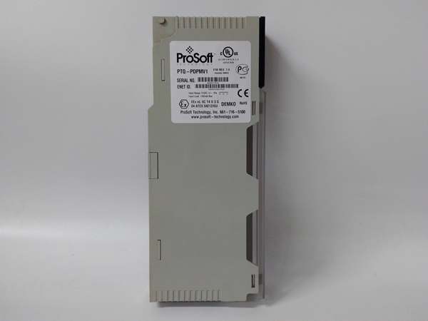
Description
Hard-Numbers: Technical Specifications
- Backplane Current Load: 1100 mA max @ 5 VDC ± 5%
- Operating Temperature: 0°C to 60°C (32°F to 140°F)
- Storage Temperature: -40°C to 85°C (-40°F to 185°F)
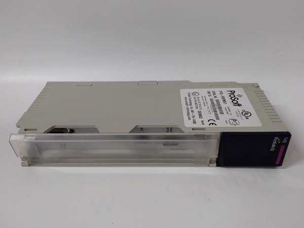
- Backplane Compatibility: Single-slot Quantum, same rack as CPU
- PROFIBUS Port: 9-pin D-sub female, optically isolated RS-485
- Baud Rate: Up to 12 Mbps (auto baud detection)
- Supported Slaves: Up to 125 (with repeaters)
- DPV1 Services: Class 1/2 acyclic parameter reads/writes, extended diagnostics, alarm indication/confirmation, Multicast/Broadcast
- Configuration/Ports: ProSoft Configuration Builder (PCB); config serial port (PRT1) DB-9M RS-232; Ethernet RJ45 for configuration, diagnostics, and hot standby UDP
- Hot Standby: Supports up to 6 modules per rack (up to 4 in HSBY); nominal switchover 100 ms (≤300 ms); auto-detects 140CPU67160 HSBY CPU
- Certifications: CE EMC EN61326-1/EN61000-6-4; cULus Class I Div 2 Groups A,B,C,D; CB IEC61010; ATEX EN60079-0/EN60079-15 Category 3 Zone 2
- Dimensions: 250 × 103.85 × 40.34 mm (9.84 × 4.09 × 1.59 in)

PTQ-PDPMV1
The Real-World Problem It Solves
This module gives Quantum processors a robust, DPV1-capable PROFIBUS DP master interface with hot standby support. It handles cyclic I/O and acyclic parameter exchanges, enabling diagnostics and alarm management without custom code. In redundant 140CPU67160 systems, it provides failover with minimal disruption (≤300 ms) and uses Ethernet to sync state between primary and standby masters. It’s a drop-in solution for integrating PROFIBUS slaves—drives, I/O, gateways, PA devices via DP/PA coupler—while keeping the backplane load manageable and providing strong diagnostics.
Where you’ll typically find it:
- Process plants with Quantum HSBY CPUs managing PROFIBUS devices (e.g., drives, remote I/O)
- Water/wastewater, power gen, and OEM machinery with mixed-device networks requiring DPV1 diagnostics and parameter access
- Upgrades or retrofits where PROFIBUS devices must coexist with new Quantum systems
The bottom line: You get a DPV1 master that plays nicely with Quantum and hot standby, offers straightforward configuration via PCB, and provides built-in diagnostics and mailbox commands to keep the network visible and manageable.
Hardware Architecture & Under-the-Hood Logic
The PTQ-PDPMV1 sits on the Quantum backplane as an Options module and includes an onboard controller to handle the PROFIBUS master role. It uses Siemens ASIC ASPC2 Step E with an Infineon C165 microprocessor. Configuration data (PROFIBUS network, Ethernet) is stored on Compact Flash. A serial config port is used only for initial Ethernet setup; after that, Ethernet is the preferred path for configuration, diagnostics, and hot standby sync. The module exposes data via backplane I/O blocks and supports mailbox messaging for acyclic DPV1 services. In HSBY, both primary and standby modules run masters on the network and exchange health/state via Ethernet UDP; switchover occurs based on FDL ping failures or faults detected by the user program.
- Processor exchanges I/O with the module via backplane input/output image blocks; mailbox commands can also be used for acyclic operations.
- Onboard controller manages the PROFIBUS DPV1 master state machine, cyclic data exchange, and token rotation.
- Serial RS-485 port communicates with slaves; supports DP/PA couplers for PA devices.
- Ethernet port enables configuration via PCB, web diagnostics, and hot standby state exchange.
- Status and error words are continuously updated; LEDs provide quick visual feedback (MSTR STAT, DBASE STAT, COM STAT, TKN HLD).
- In HSBY, the standby master monitors the primary; if the primary fails or the bus is compromised, the standby assumes control within the specified switchover window.
PTQ-PDPMV1
Field Service Pitfalls: What Rookies Get Wrong
Mixing up PTQ-PDPMV1 with unrelated gateways
Rookies assume it’s a general-purpose PROFINET or Modbus gateway. It’s a Quantum in-chassis PROFIBUS DPV1 master only.
- Field Rule: Confirm the target platform is Quantum and the field bus is PROFIBUS DP. For other protocols or platforms, choose a different ProSoft module.
Placing the module in a remote I/O (RIO) rack instead of the local rack
The PTQ module must reside in the same rack as the Quantum CPU. Installing it in a remote rack breaks backplane communication and leads to faults.
- Quick Fix: Move the module to the local rack with the CPU. Never install PTQ modules in RIO chassis.
Forgetting to connect Ethernet in hot standby systems
HSBY requires Ethernet between the two PTQ modules for UDP-based state exchange. Without this, switchover logic cannot function correctly.
- Field Rule: In HSBY, ensure both modules are on the same Ethernet network; verify connectivity from each module’s IP (standby IP = primary IP + 1 by convention) before enabling HSBY in logic.
Ignoring checksum mismatches after configuration changes
If you reconfigure the network or slaves in PCB but don’t update the checksum in the Unity/Concept project, the module 终止s and CFGERR lights up.
- Quick Fix: After any network change, recalculate checksums in PCB and update the checksum value(s) in your Unity/Concept function block before downloading to the CPU.
Misplacing terminal resistors or using the wrong baud rate
Missing terminators or mismatched bauds cause intermittent communication, packet errors, or complete bus failure.
- Field Rule: Terminate both ends of the PROFIBUS trunk; match baud rates on all devices. Use PCB diagnostics to scan the network and validate slave presence.
Not using Ethernet after initial setup and relying only on the serial config port
The serial port (PRT1) is for initial Ethernet setup only. For ongoing configuration, diagnostics, and mailbox operations, Ethernet should be used.
- Field Rule: After setting Ethernet parameters once, switch to Ethernet connections for all further configuration and monitoring. Reserve serial only for recovery scenarios.
Overlooking Compact Flash as a configuration transfer path for module swaps
When replacing a faulty PTQ, rookies try to reconfigure from scratch instead of transferring the CF card with the original configuration.
- Field Rule: In a module swap, move the CF card from the old unit to the new one to retain all configurations; verify the new module comes online and that the CFGERR LED is off.
Misinterpreting LED states during HSBY switchover
Seeing red LEDs or OFF states during a switchover can be misread as a fatal error when it’s part of the failover transition.
- Field Rule: Learn the HSBY LED patterns—specifically that ALL LEDs OFF can indicate the standby is held in reset while the primary is active; use PCB diagnostics to verify roles and health instead of relying solely on LEDs.


