
Description
Hard-Numbers: Technical Specifications
- Protocol Support: PROFIBUS DP Master (DPV0, DPV1), Backplane (PLC-5 or SLC 500)
- Port Count: 1 x PROFIBUS DP (9-pin D-Sub female), 1 x backplane connection
- Baud/Data Rate: 9.6K, 19.2K, 93.75K, 187.5K, 500K, 1.5M, 3M, 6M, 12M selectable
- Operating Temperature: 0 to +60°C (32 to 140°F)
- Storage Temperature: -40 to +85°C (-40 to 185°F)
- Isolation Rating: 1500V RMS isolation between backplane and PROFIBUS port
- Power Draw: PLC-5: 800mA @ 5VDC; SLC 500: 1.0A @ 5VDC from backplane
- Backplane Compatibility: 1771 PLC-5 chassis, 1747 SLC 500 chassis (any slot)
- Maximum Slave Devices: Up to 125 slaves per master (practical limit typically 24-32 based on data volume)
- Maximum Input Data: 244 bytes per slave
- Maximum Output Data: 244 bytes per slave
- GSD File Support: Loads standard GSD/GSDML files for device-specific configuration
- Memory Mapping: PLC-5: M0/M1 files, N files, OTE instructions; SLC 500: M0/M1 files, N files, B files
- LED Indicators: MOD (module status), BUS (PROFIBUS activity), CFG (configuration status), FAULT
- Connector Type: 9-pin D-Sub female (per IEC 61158-2)
- Dimensions: Standard single-slot PLC-5/SLC 500 form factor

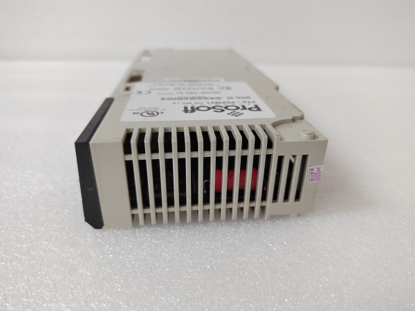
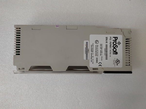
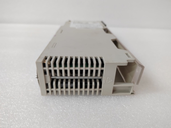
PTQ-PDPMV1
The Real-World Problem It Solves
You’ve got a PLC-5 or SLC 500 system that’s been running for 20 years, and now you need to integrate new European equipment that only speaks PROFIBUS DP. Replacing the PLC system would trigger a complete plant shutdown and validation nightmare. This module sits in the legacy rack and acts as a PROFIBUS DP master, letting your old Allen-Bradley processor control those new devices without touching the existing control logic.
Where you’ll typically find it:
- Automotive stamping plants with aging PLC-5 controls managing new Siemens drive systems
- Food processing facilities where legacy SLC 500 systems interface with European packaging and labeling equipment
- Pulp and paper mills where old PLC-5-based reel controls need to communicate with new PROFIBUS-based caliper sensors
Bottom line: It extends the life of proven PLC-5/SLC 500 systems by adding PROFIBUS capability without forcing a controller migration—keep the old iron, add the new functionality.
Hardware Architecture & Under-the-Hood Logic
This module operates as a PROFIBUS DP Master Class 1 device while communicating directly with the PLC-5 or SLC 500 processor via the backplane. The onboard processor handles all PROFIBUS protocol mechanics including token rotation, parameterization, configuration, and cyclic data exchange. Slave device parameters are loaded via standard GSD files. Data exchange with the host processor occurs through backplane data table mapping—PLC-5 uses M0/M1 files and integer files, while SLC 500 uses M0/M1 files, integer files, and bit files depending on configuration.
- The PLC-5 or SLC 500 processor reads and writes data to the module’s memory areas via backplane data table mapping.
- The onboard PROFIBUS DP master maintains the token list and initiates cyclic polling of all configured slaves at the configured baud rate.
- GSD files define slave device capabilities—input/output byte counts, supported baud rates, and diagnostic parameters.
- During startup, the master performs parameterization and configuration phases for each slave before entering data exchange mode.
- Cyclic data exchange occurs continuously, with each slave receiving output data and returning input data during its token slot.
- Data transfers between backplane memory and PROFIBUS buffers occur continuously, with the module updating backplane data tables at the backplane scan rate.
- Diagnostics are monitored continuously—slave faults, communication timeouts, or cable breaks trigger the FAULT LED and mapped diagnostic words.
PTQ-PDPMV1
Field Service Pitfalls: What Rookies Get Wrong
Backplane Power Budget OverloadThe PTQ-PDPMV1 draws 800mA (PLC-5) or 1.0A (SLC 500), and technicians load a chassis with multiple communication modules without checking the power supply budget. The power supply trips during high-activity periods, and the entire rack goes dark.
Field Rule: Calculate total backplane current draw. A standard 1771-P5R power supply delivers 8A at 5VDC. Three PTQ modules consume 2.4A—factor in your analog I/O and other high-current cards. If you’re above 70% of rated capacity, add a secondary power supply before adding more modules.
M0/M1 File Addressing ConflictsIn PLC-5 systems, the module uses M0 and M1 files for data exchange, and technicians configure file numbers that conflict with existing logic. The processor writes to the wrong memory area, unrelated logic behaves erratically, and troubleshooting becomes a nightmare.
Field Rule: Reserve M0 and M1 file ranges specifically for the PTQ module. If your existing logic uses M0 through M10, start the PTQ module at M11. Document the file ranges in your cross-reference and protect these files with write-protect if the processor supports it. Never reuse M0/M1 files that are already in use.
Missing Termination at Network EndThe module is installed at the physical end of the PROFIBUS trunk, but the technician doesn’t install a termination resistor. The bus isn’t properly terminated, signals reflect, and intermittent communication faults occur during high electrical noise conditions.
Field Rule: Terminate PROFIBUS networks at both physical ends only. If the PTQ-PDPMV1 is at the end of the trunk, install a 220Ω termination resistor bridging pin 3 and pin 8 on the D-sub connector. Verify resistance across the bus with a multimeter—approximately 110Ω on a properly terminated network (two 220Ω resistors in parallel).
Baud Rate Mismatch with SlavesThe master is configured for 12Mbps, but one slave only supports 1.5Mbps. That slave never responds, the master keeps retrying, and the entire network slows down. The technician sees “timeout” faults and assumes the cable is bad.
Quick Fix: Check the GSD file or device manual for each slave’s maximum supported baud rate. Configure the master for the lowest common denominator across all slaves. When adding new devices, match the existing network speed unless you’re upgrading every device simultaneously.
SLC 500 Data Table Size LimitsSLC 500 systems have limited data table capacity, and technicians configure massive data transfers that exceed available memory. The processor generates memory faults, and the system halts.
Field Rule: Calculate your SLC 500 data table usage before configuration. If your SLC has 32K total data file capacity and you’re using 20K, you only have 12K left. Map only the necessary data words—don’t transfer entire device databases. Use block transfers efficiently and compress data where possible.
GSD File Version MismatchTechnicians load a GSD file revision that doesn’t match the actual slave device firmware. The master configures the slave with parameters it doesn’t understand, and the slave fails initialization with “parameterization failed” faults.
Field Rule: Always verify the slave device firmware revision and load the matching GSD file version. Document which GSD version goes with each device. Maintain a GSD library organized by device model and firmware revision. When upgrading slave firmware, update the GSD file immediately.
Ignoring Backplane Scan Time ImpactThe module updates backplane data on every processor scan, but the PLC-5 or SLC 500 scan time has slowed over the years due to added logic. The PROFIBUS data becomes stale relative to the actual process, causing control loop instability.
Quick Fix: Monitor your processor scan time. If the scan has grown from 50ms to 200ms over years of modifications, the PROFIBUS data is now 200ms old. Consider time-stamping critical data or adjusting control loop timing to account for the increased latency. Document scan times during commissioning and track changes over time.
Pin 1 Ground Connection ErrorsOn 9-pin D-sub connectors, technicians mistakenly use pin 1 as the shield ground connection instead of grounding the backshell. Pin 1 is not ground in PROFIBUS—it’s sometimes used for +24V in proprietary implementations. Connecting shield to pin 1 creates ground loops and noise issues.
Field Rule: Ground the cable shield to the D-sub backshell, not pin 1. Pin 3 is B/RX/TX-P, pin 8 is A/RX/TX-N, pin 5 is signal ground. Use shielded cable with the drain wire terminated to the metal connector backshell. Never use pin 1 for shield ground in PROFIBUS applications.
Please note: The listed price is for reference only and is not binding. Final pricing and terms are subject to negotiation based on current market conditions and availability.


