
Description
Hard-Numbers: Technical Specifications
- Protocol Support: Modbus RTU (Master/Slave), Modbus ASCII (Master/Slave), Ethernet/IP (backplane)
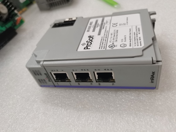
- Port Count: 2 x RS-232/485 configurable ports (Phoenix connectors), 1 x backplane connection
- Baud/Data Rate: 300 to 115.2K per serial port (selectable)
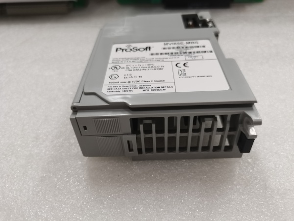
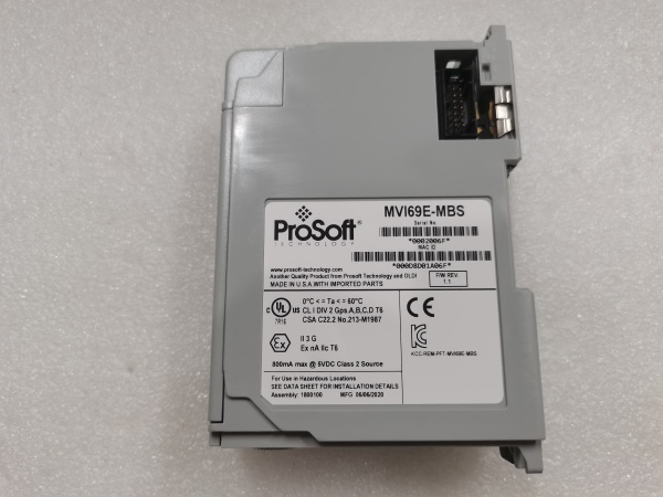
- Operating Temperature: 0 to +60°C (32 to 140°F)
- Storage Temperature: -40 to +85°C (-40 to 185°F)
- Isolation Rating: 1500V RMS isolation between backplane and serial ports
- Power Draw: 600mA @ 5VDC from CompactLogix backplane
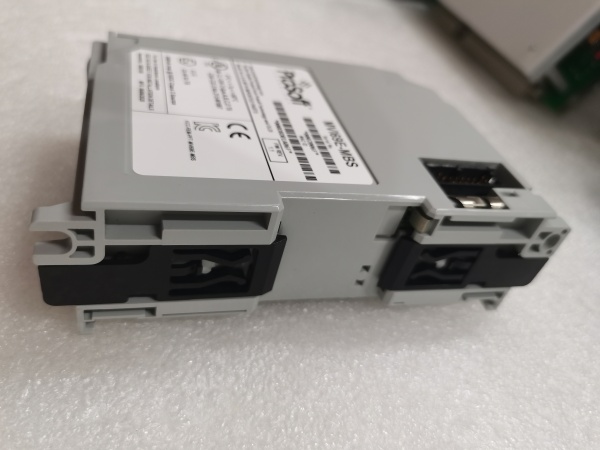
- Backplane Compatibility: 1768 CompactLogix chassis (any slot)
- Serial Port Modes: RS-232 (point-to-point), RS-485 (multi-drop, up to 31 devices per port)
- Maximum Cable Length: RS-232: 15 meters (50 feet); RS-485: 1200 meters (4000 feet)
- LED Indicators: MOD (module status), P1 (port 1 activity), P2 (port 2 activity), CFG (configuration status), FAULT
- Connector Types: 4-pin Phoenix (each serial port)
- Dimensions: Standard single-slot CompactLogix form factor

PROSOFT MVI69E-MBS
The Real-World Problem It Solves
You’ve got a CompactLogix system running a process, but critical field instrumentation—flow computers, gas analyzers, tank gauges—only speaks Modbus over serial. Replacing these devices means re-wiring runs that were installed years ago, and that’s a budget nightmare. This module lets your CompactLogix talk to those serial devices over the existing copper runs without pulling new cable or replacing proven equipment.
Where you’ll typically find it:
- Oil and gas upstream facilities with Modbus RTU flow computers and custody transfer meters on the same serial bus
- Water treatment plants where legacy chlorine analyzers, turbidity meters, and pH transmitters share serial networks
- Chemical processing facilities where Modbus-based laboratory equipment integrates with production control systems
Bottom line: It bridges the gap between modern CompactLogix control and legacy serial instrumentation without forcing a complete infrastructure overhaul—use the wires you’ve already got, upgrade the controller later.
Hardware Architecture & Under-the-Hood Logic
This module operates as a Modbus serial communication bridge, converting between Modbus RTU/ASCII on the serial ports and Ethernet/IP on the CompactLogix backplane. The onboard processor handles all protocol translation independently, with both serial ports operating simultaneously as masters or slaves. Each port can be configured independently for baud rate, parity, and mode, allowing the module to interface with different types of devices on separate networks simultaneously.
- The CompactLogix processor exchanges data with the module via backplane I/O blocks using Ethernet/IP implicit messaging.
- The onboard processor maintains independent Modbus stacks for each serial port (RTU/ASCII support).
- In master mode on port 1, the module initiates Modbus polls to connected slave devices at configured intervals.
- In slave mode on port 2, the module responds to Modbus queries from external masters, pulling data from mapped memory areas.
- Both ports operate simultaneously and independently—data from port 1 can be routed to port 2, or both can exchange data with the CompactLogix.
- The module updates backplane I/O blocks continuously at the configured RPI rate (typically 20-50ms), independent of serial timing.
- Failed connection retry logic runs per port, with configurable timeouts and retry counts for each serial device.
PROSOFT MVI69E-MBS
Field Service Pitfalls: What Rookies Get Wrong
RS-232 vs. RS-485 Pinout ConfusionWiring an RS-485 multi-drop network to the RS-232 pin configuration kills communication instantly. RS-232 uses TX, RX, and ground; RS-485 uses Data+ (D+), Data- (D-), and ground. Cross-wiring these or using the wrong ground reference creates signal conflicts and garbled data.
Field Rule: Verify the device’s serial interface before terminating. Use the Phoenix connector pinout for the MVI69E-MBS. RS-232: Pin 1 (TX), Pin 2 (RX), Pin 3 (GND). RS-485: Pin 1 (D+), Pin 2 (D-), Pin 3 (GND). Label both cable ends clearly—P1-D+, P1-D- for port 1, P2-D+, P2-D- for port 2.
Missing RS-485 Bias ResistorsOn RS-485 runs longer than 100 meters, technicians skip biasing resistors. The idle bus voltage drifts when devices are powered down, and you get intermittent communication that looks like a device fault but is actually noise susceptibility.
Field Rule: On RS-485 networks exceeding 100 meters, add bias resistors (typically 560Ω to VCC and 560Ω to ground) at one trunk end. If the MVI69E-MBS is at the network end, enable onboard bias through configuration. Otherwise, install external resistors at the physical endpoint.
RTU vs. ASCII Mode MismatchThe serial device expects Modbus RTU (binary framing), but the module is configured for ASCII (text framing). Both sides transmit, but neither parses the other’s protocol. P1 and P2 LEDs flicker, but you get zero valid data.
Field Rule: Check the device manual for the default protocol. RTU dominates industrial applications for efficiency. ASCII is sometimes used for troubleshooting with terminal programs. Configure each serial port independently to match its connected device. If in doubt, try RTU first—most industrial gear defaults to it.
Baud Rate and Parity DisagreementThe module runs at 19.2K, 8N1, but the flow computer is set for 9.6K, 8E1. Characters misalign, every frame fails CRC check, and the FAULT LED stays solid red. Technicians waste hours swapping cables before checking configuration.
Quick Fix: Verify the serial port configuration on the device itself, not just what the P&ID says. Use a laptop with a USB-to-serial adapter and terminal software to query the device directly. Confirm baud rate, data bits, parity, and 终止 bits, then match the MVI69E-MBS exactly.
Cable Length Exceeding RS-232 LimitsTechnicians run an RS-232 cable 200 feet to a remote analyzer, far exceeding the 50-foot spec. Signal degradation causes intermittent reads that look like device faults but are actually distance-related attenuation.
Field Rule: RS-232 is for short runs—under 15 meters for reliable communication. Use RS-485 for anything longer. If you must extend RS-232, install an RS-232 to RS-485 converter at both ends. Document every serial run length in your as-builts and calculate signal integrity margins.
Duplicate Device Addresses on Multi-DropTwo Modbus RTU devices on the same RS-485 bus both use address 5. The master polls address 5, both devices respond simultaneously, signals collide, and the master receives garbage. Technicians blame the master module when the issue is duplicate addressing.
Quick Fix: Verify every device address on the bus before installation. Use a Modbus scanner or diagnostic tool to survey the network and confirm no duplicates. Document addresses in your commissioning package. When adding new devices, scan the bus first to confirm the address is available.
Ground Loop Between Building SegmentsConnecting an RS-485 ground wire from a remote panel to the CompactLogix chassis ground creates ground loops. When large equipment starts nearby, potential differences inject noise, corrupting Modbus frames.
Field Rule: RS-485 should be grounded at one point only—typically the master device. If the MVI69E-MBS is the master on that port, ground it there. If it’s a slave, ensure the master provides the single-point ground. For runs between buildings, use fiber optic converters or isolated repeaters to break ground loops.
Register Offset MiscalculationA Modbus device specifies holding register 40100 for flow rate, but the configuration treats it as absolute address 40100 (which doesn’t exist) instead of register 99 with offset 40001. The module reads garbage, and flow values swing wildly.
Field Rule: Understand the addressing convention. Many manufacturers document registers as 4xxxx (holding), 3xxxx (input), 0xxxx (coil), 1xxxx (discrete input). Modbus protocol uses addresses 0-65535. A 4xxxx register typically maps to actual address (4xxxx – 40001). Test with a known value—command a 50mA setpoint and verify you read back exactly 50.
Please note: The listed price is for reference only and is not binding. Final pricing and terms are subject to negotiation based on current market conditions and availability.


