
Description
Hard-Numbers: Technical Specifications
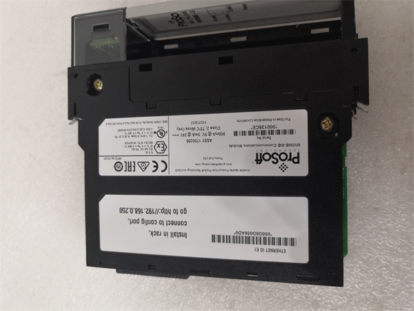
- Backplane Current Load: 800 mA @ 5 VDC; 3 mA @ 24 VDC
- Operating Temperature Range: 0°C to 60°C (32°F to 140°F)
- Storage Temperature Range: -40°C to 85°C (-40°F to 185°F)
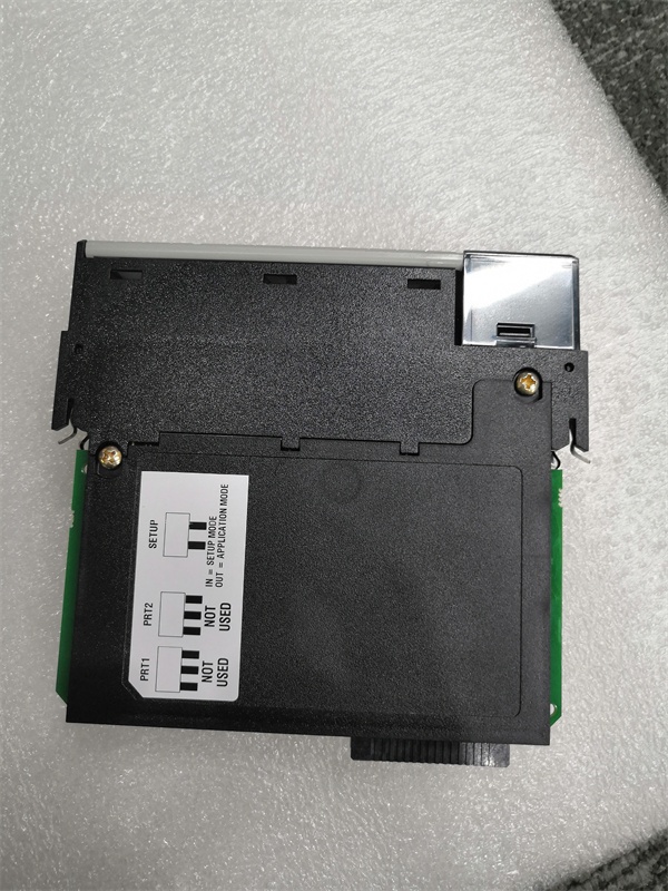
- Serial Port: One RJ45 port (configurable via jumpers as RS-232/422/485)
- Serial Data Rate: 110 bps to 115.2 kbps
- Ethernet Port: 10/100 Base-T RJ45 (EtherNet/IP; auto-crossover)
- Supported Protocols: EtherNet/IP (CIP), Modbus RTU/ASCII over the serial port (via firmware-dependent functionality)
- Data Block Size: Reduced I/O block for lower backplane/ControlNet bandwidth; database size up to several thousand 16-bit registers (exact capacity and mapping vary by firmware/version)
- Isolation Rating: 500V optical isolation from backplane on the serial port
- Certifications: CE, CULUS, ATEX (optional; check label)

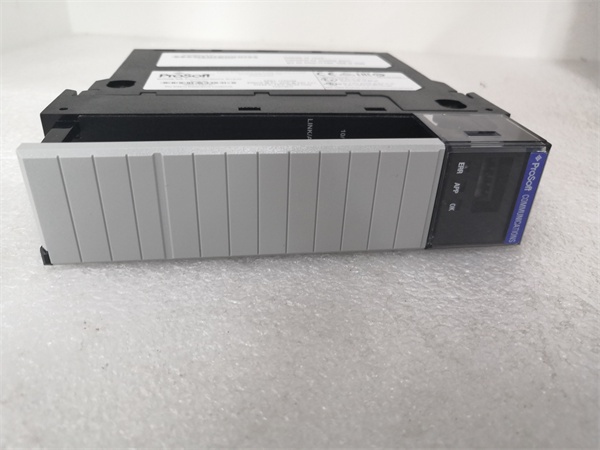
PR0S0FT MVI56E-SIE
The Real-World Problem It Solves
This module provides a straightforward way to extend an EtherNet/IP network to one serial device or small serial bus from a ControlLogix chassis. In remote racks where ControlNet bandwidth is scarce or where you only need a single serial gateway, it keeps backplane slots and overhead low. It’s ideal for connecting a legacy drive, a barcode scanner, a weigh scale, or a single Modbus meter without resorting to a full dual-port solution. CIPconnect allows remote configuration and diagnostics via 1756-ENxT bridges.
Where you’ll typically find it:
- Remote I/O chassis where adding just one serial device is required
- Connecting a single serial device to a ControlLogix system over EtherNet/IP while preserving ControlNet capacity
- Retrofits or expansions where a compact, single-port gateway is more cost-effective than a dual-port module
The bottom line: You get a focused, backplane- and bandwidth-efficient EtherNet/IP-to-serial bridge for ControlLogix that can be configured and diagnosed remotely, minimizing chassis slot usage and network overhead.
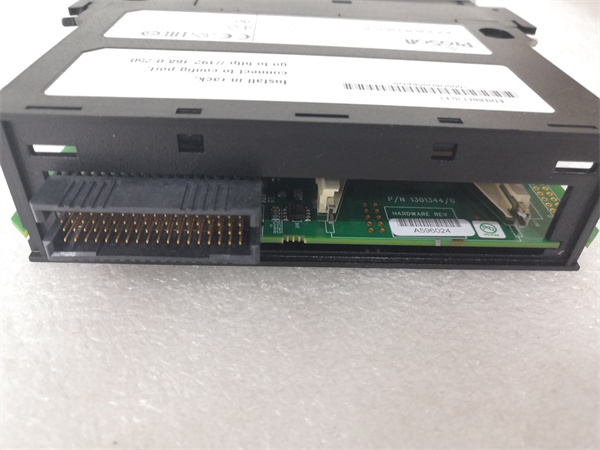
Hardware Architecture & Under-the-Hood Logic
The MVI56E-SIE occupies one ControlLogix slot and presents an onboard database and I/O image to the backplane. An onboard processor handles EtherNet/IP-to-serial conversion independently of the ControlLogix processor. The single serial port’s physical layer (RS-232/422/485) is set via hardware jumpers. The Ethernet port supports CIPconnect for remote configuration and diagnostics via ProSoft Configuration Builder (PCB) or web UI.
- ControlLogix processor exchanges scheduled I/O data with the module’s input/output image blocks.
- Onboard firmware manages the EtherNet/IP client/server connections and buffers data.
- The serial port transmits/receives data based on configuration; Modbus RTU/ASCII support depends on the loaded firmware profile.
- Status and error words are updated continuously in the database for the processor to monitor.
- Ethernet port (E1) enables configuration, diagnostics, and remote access via CIPconnect through ENxT bridges.
PR0S0FT MVI56E-SIE
Field Service Pitfalls: What Rookies Get Wrong
Confusing MVI56E-SIE with dual-port gatewaysRookies expect two serial ports and plan for multiple devices, leading to architecture changes mid-project.
- Field Rule: Confirm the single-port design upfront. If you need two independent serial buses or more devices, consider a dual-port module instead.
Overlooking jumper settings for the serial portLeaving jumpers in the default RS-232 position when wiring RS-485 results in communication failures.
- Quick Fix: Power down, verify and set the jumper to RS-485 (or RS-422) before connecting the serial bus.
Forgetting to add the module’s EDS to RSLinxWithout the EDS, RSLinx won’t recognize the module correctly, and you’ll see unknown devices or connection issues.
- Field Rule: Install the ProSoft EDS for MVI56E-SIE in RSLinx Classic before configuring or online editing.
Misconfiguring IP address and CIPconnect pathsSetting an IP outside your subnet or failing to set proper routes through ENxT modules prevents remote configuration.
- Field Rule: Use ProSoft Discovery Service (PDS) to set an initial in-subnet IP, then verify routes and reachability with PDS or a 浏览器.
Ignoring serial port isolation and wiring limitsRunning long, unshielded serial cables or exceeding segment length can cause intermittent faults.
- Field Rule: Follow RS-485/422/232 physical layer rules for termination, biasing, and cable length. Use shielded, twisted-pair cable and keep within specified segment lengths.
Not monitoring status/error words in the databaseFailing to map status and error blocks to the HMI or alarms hides communication health.
- Field Rule: Map the module’s status and error words into HMI faceplates and set up trending and alarms for non-zero values.


