
Description
Hard-Numbers: Technical Specifications
- Protocol Support : Modbus TCP (Master/Slave) + CIP (Produced/Consumed)
- Port Count : 1 × RJ45 10/100 Mbps Ethernet (背板连接,通过 ControlLogix 机架)
- Baud/Data Rate : 10/100 Mbps auto-sense
- Operating Temperature : 0°C to 60°C (32°F to 140°F)
- Storage Temperature : -40°C to 95°C (-40°F to 203°F)
- Power Draw : 5.6W, 1.1A @ 5V backplane (背板电流)
- Max Modbus TCP Connections : 16
- Register Mapping Capacity : 32768 holding registers (40001-65536)
- Data Update Rate : 10ms to 1000ms configurable
- Module Scan Time : <5ms for CIP exchange
- Dimensions : 140 × 147 × 125 mm (5.5 × 5.8 × 4.9 in)
- Weight : 0.65 kg
- Certifications : UL/cUL 508, CE, ATEX Zone 2/22 (IIB T4 Gb)
- Isolation : No optical isolation on Ethernet port; backplane isolation per ControlLogix spec

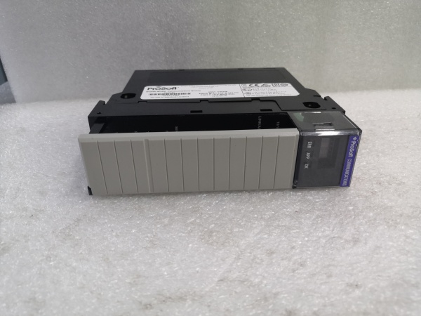
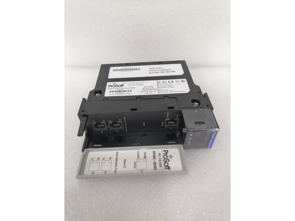
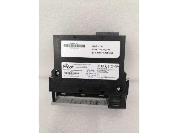
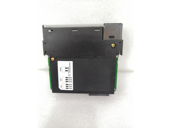
PROSOFT MV156E-MCMR
The Real-World Problem It Solves
Factory-floor headache : Your ControlLogix PLC needs to talk to Modbus TCP flow meters, drives, or SCADA head-ends. You don’t want to write custom ladder logic to construct Modbus frames or maintain 50 MSG instructions for each device. You need a native Modbus TCP interface that exposes data as CIP tags in Studio 5000.
Where you’ll typically find it:
- Water treatment plants integrating Modbus TCP flow meters into ControlLogix SCADA systems
- Oil & gas platforms bridging Modbus TCP RTU gateways to ControlLogix safety systems
- Pharmaceutical batch systems reading Modbus TCP weigh scales via Produced/Consumed tags
Bottom line : It eliminates custom ladder for Modbus TCP, giving you native CIP access to Modbus registers with no code bloat.
Hardware Architecture & Under-the-Hood Logic
The MV156E-MCMR is a ControlLogix-compatible module that mounts directly in a 1756 chassis. It has its own microprocessor and Ethernet PHY, but communicates with the Logix processor via the ControlLogix backplane using CIP Produced/Consumed tags. The Ethernet port is NOT isolated, so proper grounding and surge suppression are mandatory.
-
Power-up and backplane initialization : Module boots from internal flash, initializes Ethernet PHY, then registers with the Logix processor via backplane. LEDs indicate power, module status, Ethernet link/activity, and Modbus communication health.
-
CIP data exchange setup : In Studio 5000, you configure Produced tags (Modbus → Logix) and Consumed tags (Logix → Modbus). The module exchanges these tags with the Logix processor at the configured update rate (default 100ms). No MSG instructions needed—data flows automatically.
-
Modbus TCP Master operation : The module initiates up to 16 TCP connections to Modbus TCP slave devices (e.g., meters, drives). It polls slaves at configured intervals and maps holding/input registers to Produced tags. It handles connection timeouts and retry logic internally.
-
Modbus TCP Slave operation : The module listens for incoming TCP connections from external Modbus TCP masters (e.g., SCADA head-ends). It maps Consumed tags to Modbus holding registers, allowing external masters to read/write Logix tag values directly via Modbus.
-
Data mapping and conversion : The firmware converts between CIP tag arrays and Modbus register addressing (40001-based). You configure register-to-tag mapping via the Web GUI or Studio 5000 AOIs (Add-On Instructions). Data type conversion (INT/DINT/REAL) is handled automatically.
-
Diagnostics and fault handling : Built-in watchdog monitors Modbus connections. If a slave drops, the module flags a fault bit in the status tags and holds last-known values or sets to zero per configuration. Event logs store connection failures, CRC errors, and backplane communication errors.
PROSOFT MV156E-MCMR
Field Service Pitfalls: What Rookies Get Wrong
Ignoring backplane power budget
The MV156E-MCMR draws 1.1A @ 5V from the ControlLogix backplane. Rookies stuff it into a 1756-A10 chassis with 5 other high-draw modules, then wonder why the chassis power supply faults or the module doesn’t boot.
- Field Rule : Calculate total backplane current before installing. A 1756-A7 power supply provides 10A @ 5V. If you have 10 modules each drawing 1A, you’re at the limit. Use ProSoft’s Backplane Power Calculator spreadsheet. If you’re close, upgrade the power supply or split modules across two chassis.
Forcing high update rates
Rookies set the CIP update rate to 10ms for “real-time performance,” not realizing this floods the backplane with unnecessary traffic and causes module timeouts. The Logix processor spends too much time servicing CIP exchanges and your ladder execution time suffers.
- Field Rule : Start at 100ms default. Only go lower if you have verified backplane loading and your application truly needs sub-100ms updates. Monitor the module’s CIP scan time in Studio 5000 (Controller Tags → Module Status → Scan Time). If it exceeds 5ms consistently, raise the update rate.
Using AOIs from wrong firmware version
The MV156E-MCMR uses Add-On Instructions (AOIs) to simplify configuration in Studio 5000. Rookies import AOIs from an older firmware version, causing tag name mismatches or compilation errors. The module boots but doesn’t exchange data.
- Field Rule : Download AOIs matching your module firmware from ProSoft’s website. Check the firmware version in the Web GUI (Firmware Revision field). Import AOIs into your Studio 5000 project after upgrading the module firmware. Always keep AOIs and firmware in sync.
Not enabling Ethernet surge protection
The Ethernet port has no optical isolation. Rookies run unshielded Ethernet cables from the module directly to switches in different panels without surge suppressors. Lightning hits or VFD EMI fry the PHY transceiver.
- Field Rule : Install Ethernet surge protectors at the panel entrance. Use shielded CAT6 cables and ground the drain wire to the panel earth. If you’re in a high-EMI environment, consider fiber media converters between the panel and the switch. No isolation means you’re exposing the Logix backplane to surges—protect the entry point.
Misconfiguring Modbus register offsets
Rookies map Modbus register 40001 to Produced tag offset 0, but some devices use 40001 = register 0, others use 40001 = register 1. This causes off-by-one errors where your flow readings are zero or scrambled.
- Field Rule : Build a mapping spreadsheet before configuring in Studio 5000. Document each device’s register addressing convention. Test with a Modbus simulator software to verify register 40001 maps to the correct tag offset before going live. Most meters use 40001 = holding register 0, but some legacy drives use 40001 = register 1.
Forgetting to disable unused connections
The module supports up to 16 TCP connections. Rookies leave all 16 configured but only use 2, then wonder why the module has high memory usage and occasional timeouts. Unused connections still consume resources for keep-alive polling.
- Field Rule : Only enable the number of connections you actually need. If you have 4 Modbus devices, configure 4 connections. Disable the rest in the Web GUI. This reduces memory footprint and prevents timeout errors on dead connections.
Swapping modules without transferring configuration
Rookies pull a failed MV156E-MCMR and plug in a spare without transferring the configuration file. The new module boots with factory defaults, and production 终止s because mapping is wrong.
- Module Rule : Always back up configuration via Web GUI (Admin → Download Config) before removing any module. Store the config file on a USB drive. For spares, pre-configure them with the same firmware and settings, then store them with the config file. Swap and reboot—no reconfiguration needed.
Mixing Produced/Consumed tag data types
Rookies map a DINT tag to a 16-bit Modbus register, causing data truncation. Flow readings show only the lower 16 bits, and values max out at 32767 instead of the full range.
- Field Rule : Match tag data types to register sizes. For 16-bit Modbus registers, use INT tags. For 32-bit values, map two consecutive Modbus registers to a DINT tag. For floating point, map two registers to a REAL tag. The AOIs handle word swapping automatically—just pick the right data type.


