
Description
Hard-Numbers: Technical Specifications
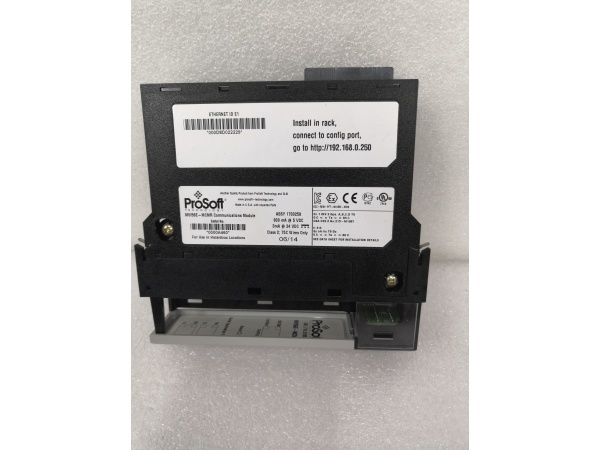
- Backplane Current Load: 800 mA @ 5 VDC; 3 mA @ 24 VDC
- Operating Temperature Range: 0°C to 60°C (32°F to 140°F)
- Storage Temperature Range: -40°C to 85°C (-40°F to 185°F)
- Data Block Size: Up to 5000 16-bit registers (user-definable mapping)
- Serial Port Data Rate: 110 bps to 115.2 kbps per port (P1, P2)
- Modbus Modes: RTU (binary with CRC-16) and ASCII (with LRC)
- Modbus Function Codes: 1, 2, 3, 4, 5, 6, 8, 15, 16, 17, 22, 23
- Command List Capacity: Up to 100 commands per Master port
- Node Address (Slave Mode) : 1 to 247 (software selectable)
- Isolation Rating: 500V optical isolation from backplane on serial ports
- Ethernet Port: 10/100 Base-T RJ45 (E1 config port; auto-crossover detection)

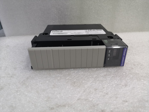
PR0S0FT MVI56E-MCMR
The Real-World Problem It Solves
This module gets ControlLogix talking to legacy Modbus devices without chewing up ControlNet bandwidth or forcing a full rework of existing programs. In remote racks over ControlNet or in redundant setups, the reduced data block keeps scheduled I/O size small while still moving data between processors and serial field devices. It also lets you configure and troubleshoot remotely via CIPconnect through ENBT/CNBT bridges—no more climbing into cabinets just to change baud rate.
Where you’ll typically find it:
- Remote ControlLogix chassis linked via ControlNet to a central processor where bandwidth is at a premium
- Plants integrating third-party drives, meters, or PLCs that only speak Modbus RTU/ASCII
- Redundant controller setups requiring consistent, low-overhead data movement across backplanes
The bottom line: You get a drop-in Modbus gateway that plays nice with existing ladder logic, saves network overhead, and can be serviced remotely through your existing EtherNet/IP infrastructure.
Hardware Architecture & Under-the-Hood Logic
The MVI56E-MCMR sits on the ControlLogix backplane as an I/O module with its own database. An onboard processor handles Modbus traffic independently of the ControlLogix processor. Data moves asynchronously between the backplane and the Modbus ports via a shared 5000-word memory map. The module supports two serial ports (P1/P2) that can each be Master or Slave, plus an Ethernet config port. CIPconnect lets ProSoft Configuration Builder (PCB) reach the module through 1756-ENxT bridges for remote diagnostics.
- ControlLogix processor exchanges scheduled I/O data with the module’s input/output image blocks.
- Onboard firmware parses Modbus commands from the internal database and executes them on P1/P2.
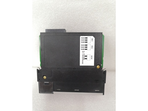
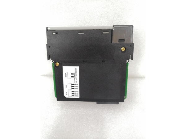
- Serial ports handle RS-232/422/485 based on jumper settings; they poll or respond per Master/Slave configuration.
- Status and error codes for each command are written back to the database for the processor to read.
- Ethernet port (E1) serves config, diagnostics, web page access, and CIPconnect traffic from a PC.
PR0S0FT MVI56E-MCMR
Field Service Pitfalls: What Rookies Get Wrong
Mixing up MVI56-MCMR and MVI56E-MCMRThe “E” and “R” suffixes matter. The E-series brings CIPconnect and web config; the R denotes reduced data block. Swapping an original MVI56-MCMR for an MVI56E-MCMR without confirming backplane bandwidth and I/O sizing can throw schedules off or cause unexpected faults.
- Field Rule: Check the module label and compare it to the project’s BOM. If replacing an older MVI56-MCMR with an MVI56E-MCMR, verify that the reduced I/O block size and existing ladder logic still match your backplane and network constraints.
Ignoring jumpers before wiring P1/P2The RJ45 serial ports default to RS-232. Rookies wire up an RS-485 multidrop without setting the onboard jumpers and wonder why the bus stays silent or flaky.
- Quick Fix: Power down, pull the module, and set P1/P2 jumpers to RS-485 (or RS-422) before connecting the field bus. Re-verify wiring against the manual pinout—DB-9 adapters can be deceptive.
Forgetting backplane power budgetAt 800 mA @ 5 VDC, this module draws noticeably more current than a standard digital input card. In a packed chassis with analog modules, you can brown out the rack if you don’t tally the 5V budget.
- Field Rule: Sum the 5V backplane current for all modules before installation. If you’re close to the power supply’s limit, consider shifting high-draw cards to another chassis or upgrading the power supply. Never assume “there’s room” without doing the math.
Misconfiguring IP and CIPconnect pathsNewbies try to hit the module’s web page over the plant network without setting a temporary IP via ProSoft Discovery Service (PDS) or without a valid route through 1756-ENxT modules.
- Field Rule: Use PDS (or check the scrolling LED for the current IP) to set an address in your subnet first. If accessing a remote chassis, verify RSLinx routes and ENxT bridging before pointing ProSoft Configuration Builder at the module.
Overlooking Command Status/Error codes in the databaseTechnicians stare at ladder logic while the module is stuffing error codes into its status words. If you don’t monitor these, you’ll chase ghosts instead of seeing that Slave ID 3 终止ped responding or that a CRC error is piling up.
- Field Rule: Map the module’s status and error words into your HMI or faceplates. Set up alarms for non-zero error counts and trending faults. Use the Data Analyzer in PCB to watch traffic in real time during commissioning.


