
Description
Hard-Numbers: Technical Specifications
- Protocol Support: PROFIBUS DP Master (DPV0, DPV1), Ethernet/IP (backplane implicit messaging)
- Port Count: 1 x PROFIBUS DP (9-pin D-Sub female), 1 x backplane connection
- Baud/Data Rate: 9.6K, 19.2K, 93.75K, 187.5K, 500K, 1.5M, 3M, 6M, 12M selectable
- Operating Temperature: 0 to +60°C (32 to 140°F)
- Storage Temperature: -40 to +85°C (-40 to 185°F)
- Isolation Rating: 1500V RMS isolation between backplane and PROFIBUS port
- Power Draw: 900mA @ 5VDC from ControlLogix backplane
- Backplane Compatibility: 1756 ControlLogix chassis (any slot)
- Maximum Slave Devices: Up to 125 slaves per master (practical limit typically 24-32 based on data volume)
- Maximum Input Data: 244 bytes per slave
- Maximum Output Data: 244 bytes per slave
- GSD File Support: Loads standard GSD/ GSDML files for device-specific configuration
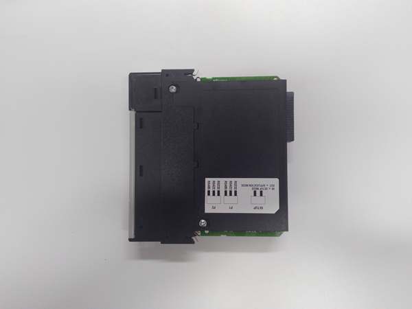
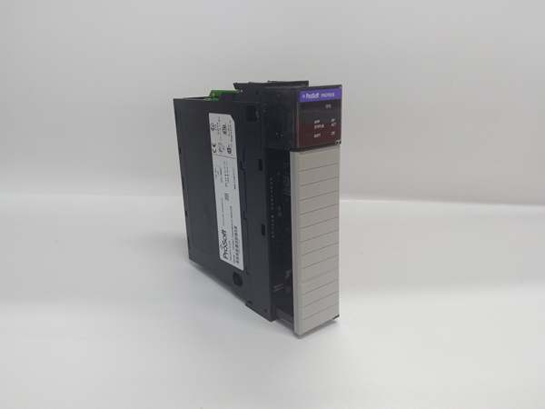
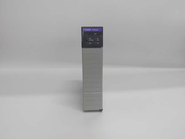
- LED Indicators: MOD (module status), BUS (PROFIBUS activity), CFG (configuration status), FAULT
- Connector Type: 9-pin D-Sub female (per IEC 61158-2)
- Dimensions: Standard single-slot ControlLogix form factor

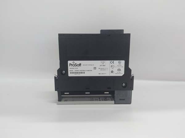
PROSOFT MVI56-PDPMV1
The Real-World Problem It Solves
You’ve got a ControlLogix-based process but purchased equipment from European manufacturers that only speak PROFIBUS DP. Rewiring to replace PROFIBUS networks with Ethernet or DeviceNet would cost a fortune and void warranties. This module lets your ControlLogix act as the PROFIBUS DP master, controlling those foreign devices directly through the existing copper infrastructure.
Where you’ll typically find it:
- Automotive assembly lines with Siemens Simatic ET200 remote I/O and Sinamics drive systems
- Food and beverage bottling plants with European packaging equipment using PROFIBUS valve networks
- Pharmaceutical manufacturing facilities with German and Swiss process equipment utilizing PROFIBUS DP instrumentation
Bottom line: It bridges the North American ControlLogix ecosystem with European PROFIBUS standards without requiring expensive network conversions or third-party controller replacements.
Hardware Architecture & Under-the-Hood Logic
This module operates as a PROFIBUS DP Master Class 1 device, managing the token-passing network while communicating with the ControlLogix processor via backplane Ethernet/IP implicit messaging. The onboard processor handles all PROFIBUS protocol mechanics including token rotation, parameterization, configuration, and cyclic data exchange. Slave device-specific parameters are loaded via standard GSD files, allowing the module to understand each device’s supported data rates, watchdog times, and diagnostic capabilities.
- The ControlLogix processor exchanges data with the module via backplane I/O blocks using Ethernet/IP implicit messaging.
- The onboard PROFIBUS DP master maintains the token list and initiates cyclic polling of all configured slaves at the configured baud rate.
- GSD files define slave device capabilities—input/output byte counts, supported baud rates, and diagnostic parameters.
- During startup, the master performs parameterization and configuration phases for each slave before entering data exchange mode.
- Cyclic data exchange occurs continuously, with each slave receiving output data and returning input data during its token slot.
- The module updates backplane I/O blocks at the configured RPI rate (typically 10-50ms), synchronizing PROFIBUS data with ControlLogix scan time.
- Diagnostics are monitored continuously—slave faults, communication timeouts, or cable breaks trigger the FAULT LED and mapped diagnostic words.
PROSOFT MVI56-PDPMV1
Field Service Pitfalls: What Rookies Get Wrong
Improper Terminator Resistor InstallationPROFIBUS DP requires termination at both ends of the trunk. Technicians leave termination off at the far end, and signals reflect back down the cable. Reflections corrupt the token passing, and you get intermittent communication faults that appear random but correlate with temperature or cable movement.
Field Rule: Install 220Ω termination resistors at both physical ends of the PROFIBUS trunk. On 9-pin D-sub connectors, pin 3 and pin 8 get bridged with the resistor. Verify resistance across the bus with a multimeter—approximately 110Ω on an idle terminated bus (two 220Ω resistors in parallel). Never terminate in the middle of a run.
Baud Rate Mismatch Across SlavesThe master is configured for 1.5Mbps, but one slave only supports 500K. That slave never responds, the master keeps retrying, and the entire network slows down. The technician sees “timeout” faults and assumes the cable is bad when the real issue is a speed mismatch.
Quick Fix: Check the GSD file or device manual for each slave’s maximum supported baud rate. Configure the master for the lowest common denominator across all slaves. If you’re adding a new slave to an existing network, match the existing network speed unless you’re upgrading every device.
GSD File Version ConflictsTechnicians load a GSD file revision that doesn’t match the actual slave device firmware. The master configures the slave with parameters it doesn’t understand, and the slave fails initialization. You spend hours troubleshooting a “parameterization failed” fault when the real problem is a GSD version mismatch.
Field Rule: Always verify the slave device firmware revision and load the matching GSD file version. Document which GSD version goes with each device. Maintain a GSD library organized by device model and firmware revision. When upgrading slave firmware, update the GSD file immediately.
Exceeding 32-Slave Address LimitPROFIBUS DP addresses range from 0-126, but technicians configure addresses 127 or higher, or duplicate addresses on the network. The master can’t address the device, token passing stalls, and the network goes completely dead.
Quick Fix: Slave addresses are decimal 0-126. Address 127 is reserved for broadcast, and 126-255 are invalid for slaves. Never duplicate addresses on the same network. Document every assigned address in your as-builts, and check for conflicts before adding new devices.
Missing Ground ReferenceFloating PROFIBUS networks cause unpredictable behavior when ground potentials differ between panels. A surge on a nearby motor induces common-mode noise, and slaves start dropping off the network randomly. The FAULT LED flickers, but cables test fine.
Field Rule: Provide a single-point ground reference for the PROFIBUS network. Ground the shield at the master end. For long runs between buildings, use fiber optic PROFIBUS repeaters to eliminate ground loops entirely. Never tie grounds from separate electrical panels together through the data cable shield.
Incorrect D-Sub Pinout WiringTechnicians wire custom cables without following the IEC 61158-2 standard. Pin 3 (B/RX/TX-P) and pin 8 (A/RX/TX-N) get swapped, or the shield lands on pin 1 instead of the backshell. Communication fails, and you waste time swapping slaves before checking the cable.
Field Rule: Follow the standard D-Sub pinout: Pin 3 = B/RX/TX-P (green), Pin 8 = A/RX/TX-N (red), Pin 5 = Ground, Shield = backshell. Use a cable tester before installation. Test continuity on both ends—pin 3 should go to pin 3, pin 8 to pin 8. Label your cable ends clearly with “P” and “N” to prevent reverse connections.
Ignoring Diagnostics MappingThe module provides comprehensive diagnostic data from each slave, but technicians only map input/output data words and ignore diagnostics. When a slave fails, there’s no indication which device or why, and troubleshooting becomes a shotgun process of disconnecting devices until the network comes back.
Quick Fix: Map diagnostic words from each slave into your ControlLogix logic. The MVI56-PDPMV1 provides standard diagnostic codes that identify the slave address, fault type, and extended diagnostic information. Use this data in your HMI for quick fault identification—knowing “Slave 12: Short Circuit” saves hours of hunting.
Please note: The listed price is for reference only and is not binding. Final pricing and terms are subject to negotiation based on current market conditions and availability.


