
Description
Hard-Numbers: Technical Specifications
- Protocol Support: Modbus RTU (Master/Slave), Modbus ASCII, Modbus TCP (Client/Server), Ethernet/IP (backplane)
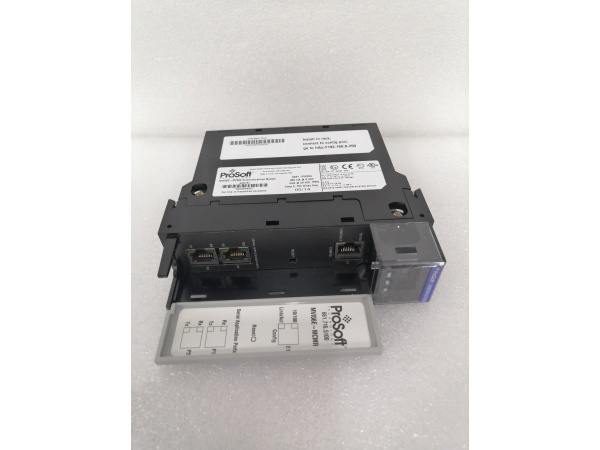
- Port Count: 1 x 10/100BaseTX (RJ45), 1 x RS-232/485 configurable port (Phoenix connector)
- Baud/Data Rate: 10/100 Mbps Ethernet; 300 to 115.2K serial (selectable)
- Operating Temperature: 0 to +60°C (32 to 140°F)
- Storage Temperature: -40 to +85°C (-40 to 185°F)
- Isolation Rating: 1500V RMS isolation between backplane and all communication ports
- Power Draw: 850mA @ 5VDC from ControlLogix backplane
- Backplane Compatibility: 1756 ControlLogix chassis (any slot)
- Serial Port Modes: RS-232 (point-to-point), RS-485 (multi-drop, up to 31 devices)
- Maximum Cable Length: RS-232: 15 meters (50 feet); RS-485: 1200 meters (4000 feet)
- LED Indicators: MOD (module status), ETH (Ethernet activity), SER (serial activity), CFG (configuration status), FAULT
- Connector Types: RJ45 (Ethernet), 4-pin Phoenix (serial)
- Dimensions: Standard single-slot ControlLogix form factor

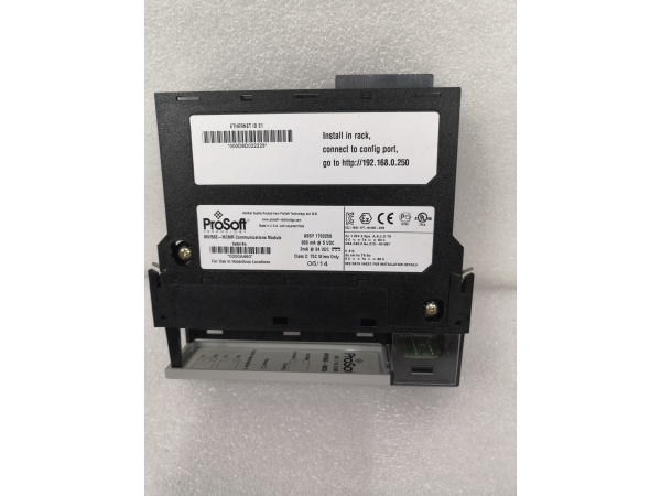
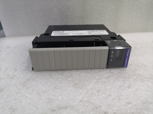
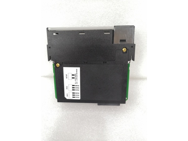
PROSOFT MVI56-MCMR
The Real-World Problem It Solves
You’ve got legacy serial devices scattered across the plant that still work perfectly but only speak Modbus RTU over RS-485. Replacing them would cost a fortune and require complete re-wiring. This module lets your ControlLogix system talk to those old devices over existing copper runs while also providing a path to Ethernet for future upgrades.
Where you’ll typically find it:
- Oil and gas upstream facilities with Modbus RTU flow computers and custody transfer meters
- Water treatment plants where legacy chlorine analyzers and turbidity meters use serial connections
- Pharmaceutical manufacturing with Modbus RTU laboratory equipment connected to production control systems
Bottom line: It extends the life of proven serial equipment while bridging to modern Ethernet infrastructure, buying you time for phased equipment replacement without process interruption.
Hardware Architecture & Under-the-Hood Logic
This module operates as a true protocol bridge, converting between Modbus RTU on the serial port and Modbus TCP on the Ethernet port, while maintaining Ethernet/IP communication with the ControlLogix backplane. The onboard processor handles all translation independently, with configurable routing that allows data to flow between serial and Ethernet ports or from either port to the ControlLogix processor. The serial port can operate as either master (initiating polls) or slave (responding to queries).
- The ControlLogix processor exchanges data with the module via backplane I/O blocks using Ethernet/IP implicit messaging.
- The onboard processor maintains independent Modbus stacks for serial (RTU/ASCII) and Ethernet protocols.
- In serial master mode, the module initiates Modbus RTU polls to connected slave devices at configured intervals.
- In serial slave mode, the module responds to Modbus RTU queries from external masters, pulling data from mapped memory areas.
- Simultaneously, the Ethernet port handles Modbus TCP client or server operations independent of serial activity.
- Data routing is configurable—serial data can be mapped to Ethernet, Ethernet to serial, or both to ControlLogix tags.
- The module updates backplane I/O blocks continuously at the configured RPI rate (typically 20-100ms), independent of serial timing.
PROSOFT MVI56-MCMR
Field Service Pitfalls: What Rookies Get Wrong
RS-232 vs. RS-485 Wiring ConfusionWiring an RS-485 multi-drop network to the RS-232 pin configuration kills communication instantly. RS-232 uses TX, RX, and ground; RS-485 uses Data+ (D+), Data- (D-), and ground. Cross-wiring these or using the wrong ground reference creates a two-way signal path that results in garbage data or complete silence.
Field Rule: Verify the device’s serial interface before terminating. Use the Phoenix connector pinout diagram for the MVI56-MCMR. RS-232: Pin 1 (TX), Pin 2 (RX), Pin 3 (GND). RS-485: Pin 1 (D+), Pin 2 (D-), Pin 3 (GND). Label your cable ends clearly—you’ll thank yourself during the 2 a.m. fault call.
Missing RS-485 Bias ResistorsOn long RS-485 runs, the idle state voltage drifts without proper biasing, causing intermittent communication failures. Technicians see it work during commissioning but fail during production when temperature changes affect the floating bus.
Field Rule: On RS-485 networks longer than 100 meters, add bias resistors (typically 560Ω to VCC and 560Ω to ground) at one end of the trunk. If the MVI56-MCMR is at the network end, enable the onboard bias through configuration. Otherwise, install external resistors at the physical endpoint.
Incorrect Grounding Between SegmentsConnecting an RS-485 ground wire from a remote panel to the ControlLogix chassis ground creates ground loops. When a large motor starts nearby, potential differences inject noise into the serial bus, corrupting Modbus frames.
Quick Fix: RS-485 should be grounded at one point only—typically the master device. If the MVI56-MCMR is the master, ground it there. If it’s a slave, use an isolated RS-485 converter or ensure the master provides the single-point ground. Never tie grounds from separate building panels together through the data cable shield.
RTU vs. ASCII Mode MismatchThe serial device expects Modbus RTU (binary framing), but the module is configured for ASCII (text framing). Both sides transmit, but neither can parse the other’s protocol. You see activity on the SER LED but get no valid data.
Field Rule: Check the device manual for the default protocol. RTU is more common in industrial applications due to efficiency. ASCII is sometimes used for troubleshooting with terminal programs. Configure the MVI56-MCMR to match the device. If in doubt, try RTU first—most industrial gear defaults to it.
Baud Rate and Parity DisagreementThe module runs at 19.2K, 8N1 (8 data bits, no parity, 1 终止 bit), but the flow computer is set for 9.6K, 8E1. Characters are misaligned, and every frame fails CRC check. The FAULT LED stays solid red.
Quick Fix: Verify the serial port configuration on the device itself, not just what the commissioning document says. Use a laptop with a USB-to-serial adapter and terminal software to query the device directly. Once you confirm it talks at 9.6K, 8E1, match the MVI56-MCMR to those exact settings.
Cable Length Exceeding RS-232 LimitsTechnicians run an RS-232 cable 150 feet to a remote panel, exceeding the 50-foot specification. Signal degradation causes intermittent reads that look like device faults. It works at 2 a.m. when electrical noise is low but fails at 2 p.m. when production peaks.
Field Rule: RS-232 is for short runs—under 15 meters for reliable communication. Use RS-485 for anything longer. If you must extend RS-232, use an RS-232 to RS-485 converter at both ends. Document every serial run length in your as-builts.
Register Mapping Without Address OffsetA Modbus device specifies holding register 40100 for flow rate, but the configuration treats it as an absolute address. The module reads register 40100 (which doesn’t exist) instead of register 100 with offset 40001, and returns zeros or garbage.
Field Rule: Understand the addressing convention. Many manufacturers document registers as 4xxxx (holding), 3xxxx (input), 0xxxx (coil), 1xxxx (discrete input). The actual Modbus protocol uses addresses 0-65535. A 4xxxx register typically maps to actual address (4xxxx – 40001). Test with a known value to confirm your offset calculation.
Please note: The listed price is for reference only and is not binding. Final pricing and terms are subject to negotiation based on current market conditions and availability.


