
Description
Hard-Numbers: Technical Specifications
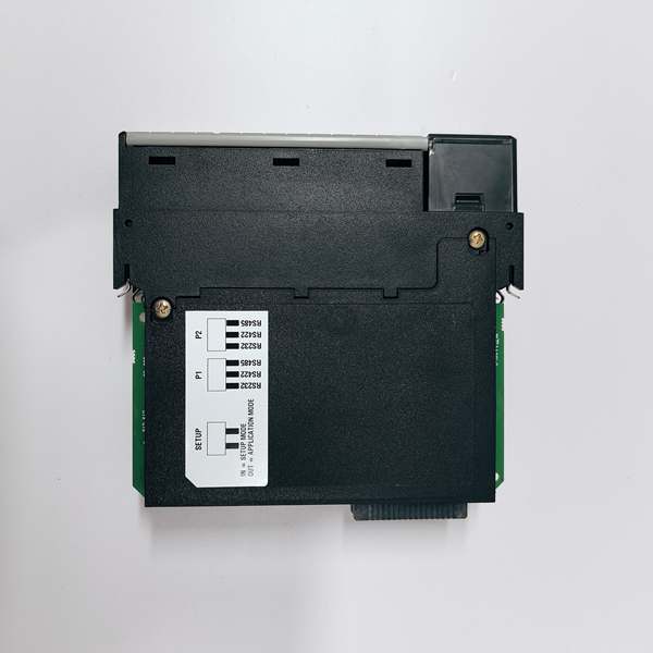
- Protocol Support: DH+ (Data Highway Plus), Remote I/O (RIO), Ethernet/IP (backplane)
- Port Count: 2 x DH+ ports (blue Phoenix connector), 1 x backplane connection
- Baud/Data Rate: 57.6K, 115.2K, or 230.4K selectable per DH+ port
- Operating Temperature: 0 to +60°C (32 to 140°F)
- Storage Temperature: -40 to +85°C (-40 to 185°F)
- Isolation Rating: 1500V RMS isolation between backplane and DH+ ports
- Power Draw: 950mA @ 5VDC from ControlLogix backplane
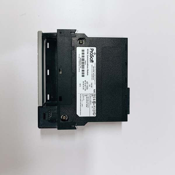
- Backplane Compatibility: 1756 ControlLogix chassis (any slot)
- Node Address Range: 0-77 octal per DH+ port
- Maximum Node Count: Up to 64 nodes per DH+ network
- Cable Length: Up to 3000 meters (9843 feet) at 57.6K baud with proper termination
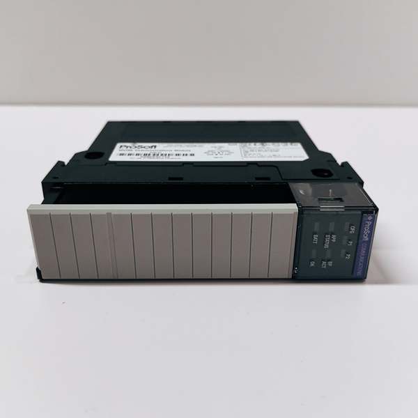
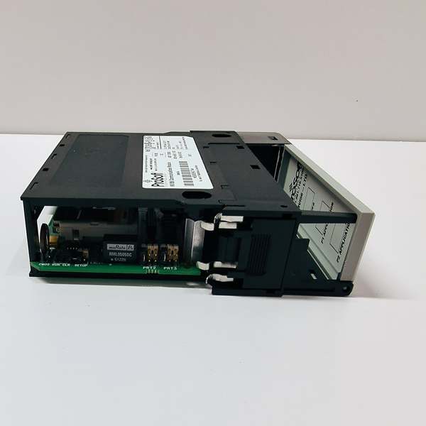
- LED Indicators: MOD (module status), PRT1 (port 1 activity), PRT2 (port 2 activity), CFG (configuration status), FAULT
- Connector Type: 3-pin Phoenix contact for each DH+ port
- Dimensions: Standard single-slot ControlLogix form factor

PROSOFT MVI56-LTQ
The Real-World Problem It Solves
You’re running a ControlLogix system but still have critical PLC-5 or SLC 500 processors on the plant floor. Replacing them all at once isn’t in the budget, and you need to pass data back and forth during a phased migration. This module lets your new controllers talk to the old ones without tearing out the existing DH+ network infrastructure.
Where you’ll typically find it:
- Automotive assembly lines where PLC-5s control legacy welding robots and ControlLogix runs newer inspection stations
- Steel mills with SLC 500s handling furnace controls while ControlLogix manages rolling operations
- Food and beverage plants migrating from PLC-5 HMI systems to modern ControlLogix-based SCADA
Bottom line: It buys you time for staged migrations by keeping legacy Allen-Bradley equipment integrated without ripping and replacing the entire network backbone.
Hardware Architecture & Under-the-Hood Logic
This module connects to the ControlLogix backplane via Ethernet/IP implicit messaging while maintaining two independent DH+ ports for legacy network integration. The onboard processor handles all DH+ protocol conversion independently, acting as a bridge that translates between the ControlLogix tag-based memory and the PLC-5/SLC file-based addressing scheme. Each DH+ port operates as a separate network segment with configurable node addresses.
- The ControlLogix processor reads and writes data to the module’s I/O memory blocks via backplane connection.
- The onboard processor maps these memory blocks to PLC-5/SLC data table addresses (N7, F8, B3 files, etc.).
- DH+ port 1 initiates or responds to token-passing traffic on the legacy network, exchanging messages with PLC-5 and SLC 500 processors.
- DH+ port 2 can operate independently on a separate DH+ network or provide redundancy for critical applications.
- Data transfers between the two DH+ ports can be configured for pass-through functionality, enabling communication between two legacy networks through the ControlLogix backbone.
- The module continuously updates backplane I/O blocks at the configured RPI rate (typically 20-50ms), while DH+ message timing is managed by the token-passing protocol overhead.
PROSOFT MVI56-LTQ
Field Service Pitfalls: What Rookies Get Wrong
Incorrect Baud Rate MismatchSetting the module for 230.4K while the rest of the DH+ network runs at 57.6K causes complete communication failure. The token never passes, and every PLC on the network goes into fault.
Field Rule: Verify the network baud rate on existing PLC-5 or SLC 500 processors before configuring the MVI56-LTQ. Check the channel configuration on at least two nodes—never assume the entire network matches one processor’s setting.
Swapped DH+ Port ConnectionsCrossing the blue Phoenix connectors between port 1 and port 2 scrambles your network addressing. You end up with messages routed to the wrong segment, and controllers start throwing “node not responding” faults because the module thinks it’s on network A while physically connected to network B.
Quick Fix: Label both cable ends clearly—P1-TR (transmit) and P1-RC (receive) for port 1, P2-TR and P2-RC for port 2. Use a continuity tester on new installations to verify signal paths match your wiring documentation.
Termination Resistor ConfusionDH+ networks require termination at both ends of the trunk, typically 150 ohms. Adding a termination resistor at the module when it’s in the middle of the network kills signal integrity, and forgetting termination when the module is at the end causes reflections that corrupt packets.
Field Rule: Map your DH+ network topology before installation. Terminate only the physical endpoints. If the MVI56-LTQ is at an end of the trunk, enable the onboard termination. If it’s in the middle, leave it disabled. Document where every resistor is installed.
Ignoring Octal Addressing LimitsDH+ node addresses are octal (0-77), but technicians configure node 64 or 128 decimal, which don’t exist in octal. The module accepts the invalid address but can’t communicate on the network, and you spend hours troubleshooting a ghost node.
Quick Fix: Remember DH+ addresses are octal—valid nodes are 00 through 77. When configuring multiple modules on the same network, double-check for duplicate octal addresses. Two devices with node 10 decimal (octal 12) and node 12 decimal (octal 14) are fine, but two modules both configured for what you think is “10” will collide.
Backplane Power StarvationAt 950mA draw, this module is power-hungry. Loading a chassis with multiple MVI56-LTQ modules plus analog I/O can push a 1756-PA72 power supply to its limit, especially in high-temperature environments where supply derating applies.
Field Rule: Calculate your power budget worst-case. A PA72 delivers 8A at 5VDC, but derate to 6.4A at 60°C ambient. Two MVI56-LTQ modules consume 1.9A—factor in your other high-current cards. If you’re pushing 80% of rated capacity, add a secondary power supply.
File Addressing Translation ErrorsMapping ControlLogix tags to PLC-5 data files without understanding file types causes data corruption. Writing a floating-point value to an integer file (N7) in the PLC-5, or trying to read a string file through the bridge, generates garbage data or faults.
Quick Fix: Know your legacy processor’s memory layout. PLC-5 integer files are N, floating-point is F, binary is B. Map the correct file type and element number. Test with known values—write 100.0 to an F8:0 element and read it back before putting the system into production.
Please note: The listed price is for reference only and is not binding. Final pricing and terms are subject to negotiation based on current market conditions and availability.


