
Description
Hard-Numbers: Technical Specifications
- Protocol Support : Modbus TCP (Client/Server) + Modbus RTU (Master/Slave)
- Port Count : 1 or 2 × RJ45 10/100 Mbps Ethernet; 1 × RJ45 RS-485 (RS-232 optional)
- Baud/Data Rate : 300-115200 bps (RTU), 10/100 Mbps (TCP)
- Operating Temperature : 0°C to 60°C (32°F to 140°F)
- Storage Temperature : -40°C to 85°C (-40°F to 185°F)
- Humidity : 5% to 95% RH non-condensing
- Power Draw : 12-24 VDC, typical 2.5W, 210 mA @ 12V or 105 mA @ 24V
- Isolation : 1500V optical isolation on RS-485 port (per datasheet)
- Max Modbus TCP Connections : 16
- Max Modbus RTU Nodes : 32
- Register Mapping Capacity : 32,768 holding registers
- Dimensions : 108 × 117 × 32 mm (4.25 × 4.61 × 1.26 in)
- Weight : 0.28 kg

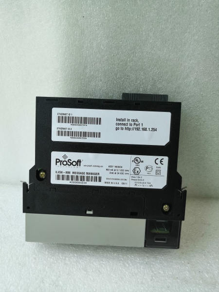
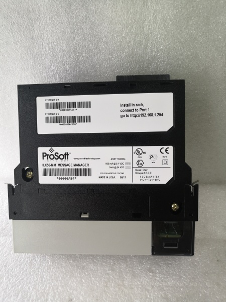
PROSOFT ILX56-MM
The Real-World Problem It Solves
Factory-floor headache : Your SCADA system speaks Modbus TCP over EtherNet/IP, but your field devices—flow meters, VFDs, legacy PLCs—still use Modbus RTU over RS-485. Rewiring everything to IP or replacing hardware isn’t an option. You need a gateway that translates between the two worlds without adding latency that kills your PID loops.
Where you’ll typically find it:
- Water treatment plants bridging flow meters and analyzers to Modbus TCP SCADA
- Oil & gas terminal units integrating legacy RTU equipment into TCP-based DCS
- Manufacturing floors adding IP-based HMIs to existing Modbus RTU VFD networks
Bottom line : It keeps your RTU infrastructure alive while giving you modern TCP connectivity, with no code changes on either end.
Hardware Architecture & Under-the-Hood Logic
The ILX56-MM is a standalone DIN-rail gateway with an embedded processor running the Modbus bridge firmware. It does not sit on any PLC backplane. The RS-485 port is optically isolated (1500V) to protect against ground loops and surges—critical in plants with poor grounding schemes. Ethernet ports are non-isolated, so pay attention to your switch grounding.
-
Power-up initialization : The module boots from internal flash, loads configuration from NVRAM, then brings up the Ethernet PHY and RS-485 transceiver. LEDs indicate power, Ethernet link/activity, and serial port status.
-
Modbus TCP connection establishment : In Client mode, the ILX56-MM initiates up to 16 TCP connections to target servers (e.g., a PLC or SCADA head-end). In Server mode, it listens for incoming TCP connections and responds to requests from external Modbus TCP masters.
-
Modbus RTU polling cycle : In Master mode, the gateway polls up to 32 RTU slave devices over RS-485 at the configured baud rate and parity. It queues requests and manages inter-frame delays to respect Modbus timing rules (t3.5). In Slave mode, it waits for commands from an external RTU master and forwards data to the TCP side.
-
Data mapping and conversion : The firmware uses a 32,768-register mapping table to translate Modbus function codes between TCP and RTU domains. For example, a TCP read of holding register 40001 might be mapped to an RTU read of register 40100 on Slave ID 5. Mapping is bidirectional and configurable via Web GUI.
-
Diagnostics and fault handling : Built-in watchdog timers monitor both networks. If TCP connections drop or RTU slaves 终止 responding, the gateway flags faults and can be configured to send exception responses or hold last-known values. Event logs are stored in NVRAM for troubleshooting.
PROSOFT ILX56-MM
Field Service Pitfalls: What Rookies Get Wrong
Reversing RS-485 polarity on the RJ45
The RJ45 connector for RS-485 follows a non-standard pinout depending on the variant you ordered. Technicians assume it’s like a standard Ethernet cable and wire A/B backward. The gateway shows no serial errors, but RTU devices don’t respond at all.
- Field Rule : Verify the pinout in the datasheet—pinout varies by factory revision. Use your multimeter to identify Data+ (A) and Data- (B) before wiring. If you get zero responses, swap the pair. This is the #1 cause of “dead network” calls on first power-up, especially in retrofit projects.
Forgetting termination on RS-485 daisy-chains
Long RS-485 runs need a 120Ω resistor at both ends of the bus. Rookies leave one end open, then wonder why communications get flaky after 1000 feet. Reflections cause data corruption that looks like intermittent failures in the SCADA historian.
- Field Rule : Measure bus length with a toner if you’re not sure. If the run is over 1000 meters (3280 ft), install 120Ω termination at both ends. Many devices have built-in termination jumpers—check if your RTU slaves have them enabled before adding external resistors. Double termination kills the bus too, so confirm only two resistors exist.
Mixing ground references between RS-485 segments
Plants with multiple building entrances or separate power feeds often have ground potential differences. Rookies tie the RS-485 ground from one panel to another without isolation, creating ground loops that fry the gateway’s transceiver over time or cause intermittent comms failures.
- Field Rule : Use the ILX56-MM’s optical isolation to your advantage. Keep the gateway’s RS-485 ground floating—do not tie it to the panel ground unless you’re absolutely certain both sides share the same reference. If you must ground for ESD protection, use a single-point ground at the gateway only. Isolation is there for a reason; don’t bypass it.
Setting inter-character timeout too aggressive
Modbus RTU requires t3.5 idle time between frames. If you configure the inter-character timeout too low in the Web GUI (e.g., 3 ms on a 9600-baud network), the gateway interprets gaps in responses as end-of-frame and sends partial data to the TCP side. SCADA sees garbage values.
- Field Rule : Set the inter-character timeout to at least 4 times the character time at your baud rate. At 9600 bps with 8N1, one character time is ~1.04 ms, so set timeout to 5 ms or higher. At 115200 bps, you can go tighter (0.5 ms). Let the gateway auto-calculate if you’re not sure—the default is usually safe for most applications.
Not accounting for register offset differences
Modbus TCP addresses often start at 0 or 1, while RTU devices use 40001-based addressing. Rookies map TCP register 0 directly to RTU register 0, then wonder why SCADA reads the wrong data point. Offsets by device type (meters, drives, PLCs) vary wildly.
- Field Rule : Build a mapping spreadsheet before touching the Web GUI. List each RTU device, its slave ID, the register range it uses, and the corresponding TCP register range the SCADA expects. Pay attention to the addressing convention: some devices use 40001 = holding register 0, others use 40001 = register 1. Test with a Modbus simulator or the gateway’s diagnostic page before going live.
Enabling TCP Keep-Alive without checking device capabilities
The ILX56-MM supports TCP Keep-Alive to detect stale connections. Rookies enable it on all 16 TCP connections without verifying that the target PLC or SCADA server supports it properly. Some devices drop connections when they receive unexpected Keep-Alive packets, causing constant reconnect loops.
- Field Rule : Test Keep-Alive on one connection at a time. Start with the default settings (idle time 2 hours, interval 75 sec). If you see connection drops or error logs showing “unexpected FIN packets,” disable Keep-Alive for that device. Not all TCP stacks implement RFC 1122 the same way, especially older PLC firmware revisions.
Ignoring the Web GUI 浏览器 cache
After changing configuration in the Web interface, rookies hit “Save” and immediately test without refreshing the page. The 浏览器 shows the old values, leading to “it didn’t take” confusion. Worse, some 浏览器s cache the JavaScript and the Apply button doesn’t trigger the actual upload.
- Field Rule : After saving configuration, force-refresh the (Ctrl+F5 or use incognito mode) before verifying settings. If you’re not sure the change stuck, reboot the gateway and check the values again. A hard reboot forces the gateway to reload from NVRAM and guarantees what you see is what’s running.
Overloading the RS-485 bus with too many nodes
The spec says 32 RTU slaves, but that’s under ideal conditions with short cables and proper termination. Rookies daisy-chain 40+ devices on a single bus, then complain about slow response times or timeouts during peak production when the network loading spikes.
- Field Rule : Count nodes, then add 20% headroom. If you have 25 devices, consider a second gateway or split the bus into two segments with repeaters. High baud rates (115200) reduce maximum distance, so trade off speed vs. length. Start at 19200 for most plant networks—you won’t notice the latency difference, but you’ll see fewer CRC errors.
标价非实价,根据市场行情可适当议价出售


