
Description
Hard-Numbers: Technical Specifications
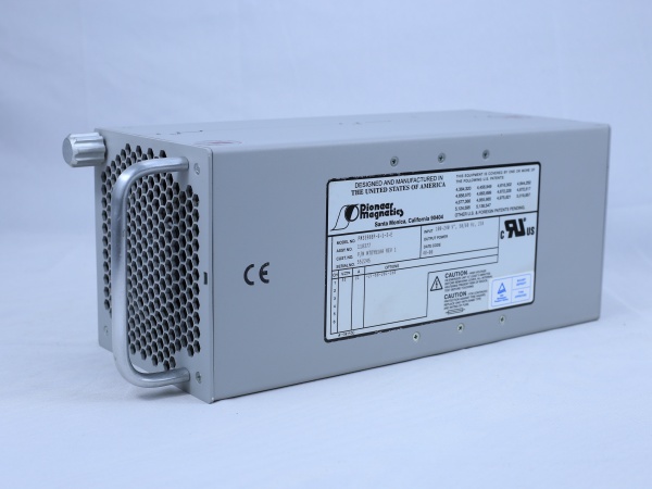
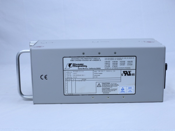
Note: Below values are reported by vendor pages and are inconsistent. Do not apply power until you verify against the unit nameplate and manual.
- Input Voltage Range: 100–240 V AC, 50/60 Hz (common listing)
- Output Voltage: Reported as 24 V DC and 56 V DC in different sources (major conflict)
- Output Current: 6–26.8 A depending on source (high variance)
- Output Power: Up to ~1500 W claimed (one source)
- Efficiency: 90–98% (varies; confirm from manual)
- Operating Temperature Range: –40 to +85°C (frequently cited)
- Storage Temperature Range: –55 to +125°C (often listed)
- Protection Rating: IP20 to IP67 across sources; inspect physical housing and connectors
- Dimensions: Conflicting reports from 110×60×30 mm to 170×160×70 mm
- Weight: 0.1–1.2 kg (varies by source)
- Communication: Some pages mention RS485/Modbus/RS232; verify port presence and wiring plan
- Protection Features: OVP, OCP, OTP mentioned; confirm LED/fault behavior from manual

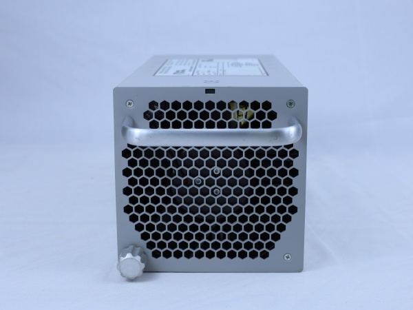
PIONEER MAGNETICS PM3398BP-6-1-3-E
The Real-World Problem It Solves
If it is a power module, it provides a compact, wide-input DC source to run PLC racks, I/O, or small drives in distributed panels. If it’s a control/interface module, it bridges field devices to controllers with some isolation and signal conditioning. Either way, it’s meant to survive harsh environments and keep control systems alive when mains are dirty or space is tight.
Where you’ll typically find it:
- Distributed I/O cabinets with limited space needing 24 or 56 V DC power
- Robot cells or machinery where a small power front-end or interface card is required
- Remote skids or enclosures with RS485/Modbus field devices needing a gateway or supply
Bottom line: It could be the difference between a dead rack and a running line—but only if you confirm the specs and wiring before you throw the breaker.
Hardware Architecture & Under-the-Hood Logic
Assuming it behaves like a compact switching power or control module: it takes the AC mains, rectifies and filters it, chops it at high frequency through a transformer or magnetics stage, then regulates the DC output with feedback. If it has a communication port, there may be a small MCU handling protocol translation and status reporting. Whether it is fully isolated depends on the variant; some pages claim isolation, others suggest direct integration.
- AC input passes through EMI filtering and a rectifier stage.
- High-frequency switching (tens to hundreds of kHz) steps the voltage down.
- Output rectification and LC filtering produce the regulated DC rail.
- Feedback loops sense output voltage/current and adjust duty cycle.
- If equipped, a control section handles RS485/RS232 and reports status/faults.
PIONEER MAGNETICS PM3398BP-6-1-3-E
Field Service Pitfalls: What Rookies Get Wrong
Trusting the spec sheets from random resellersOnline vendors list wildly different voltages, currents, and dimensions. Rookies treat these as gospel and fry a module or mis-size a breaker.
- Field Rule: Always read the nameplate and, if possible, the official manual. If you can’t find the manual, measure output at no-load (carefully) and verify voltage before connecting loads.
Mixing up the BP and 6P variantsThe PM3398B-6-1-3-E, PM3398BP-6-1-3-E, and PM3398B-6P-1-3P-E are not interchangeable. Some listings conflate them, and swapping can cause incompatibility or damage.
- Field Rule: Cross-reference the full model string and any suffix on the label with your system’s BOM. If a manual or diagram exists, follow the exact part number—no guessing.
Ignoring thermal derating and mountingRunning these at the upper end of their temperature range without airflow or proper heatsinking will trigger thermal shutdowns or shorten life.
- Field Rule: Mount with clearance for convection or forced air. If ambient is above 40–50°C, derate current per the manual. Watch the fault LED behavior under load.
Skipping protection checks before power-upAssuming OVP/OCP/OTP are set correctly can lead to cascading failures when a fault occurs.
- Field Rule: Verify protection functions with a controlled test (current limit, short) if the manual provides guidance. Never assume; verify with a meter and, if safe, a brief fault simulation.
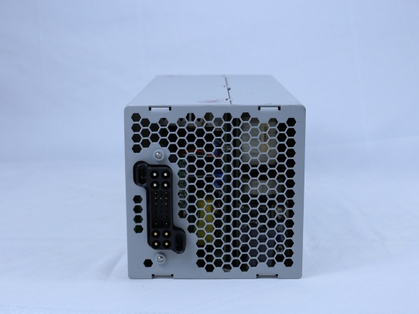
Miswiring communication portsSome references mention RS485/RS232; connecting 24 V DC to a comm port will kill the interface.
- Field Rule: Identify each port with a meter before wiring. Follow the pinout from the manual—do not rely on color-coded cables from different vendors.


