
Description
Hard-Numbers: Technical Specifications
Electrical Specifications
-
Power Input:
- Operating Voltage: 24 VDC control logic / 200-240 VAC main power
- Frequency Range: 50-60 Hz
- Input Current: 5A rated (CPX2500S variant specifications)
- Power Rating: 2500W maximum output power
- Control Power: 24 VDC ±10% (for control electronics)
- Mains Input: Single-phase 200-240 VAC with neutral and ground
-
Motor Output:
- Continuous Current: 5A RMS (rated)
- Peak Current: Up to 10-15A (short-term, specification variant dependent)
- Drive Type: PWM inverter with vector control
- Output Voltage: 3-phase PWM (derived from DC bus, approximately 200-240 VAC equivalent)
- Switching Frequency: 10-20 kHz PWM (typical for COMPAX-S series)
- Torque Control: Precision torque regulation via vector control algorithm
-
Control Specifications:
- Control Type: Vector control (FOC – Field Oriented Control)
- Control Modes: Position, Velocity, Torque control modes
- Positioning Accuracy: ±0.01% (0.01mm resolution cited in some specifications)
- Speed Range: 0-6000 RPM (rated speed range)
- Encoder Compatibility: Sin/Cos, HTL, 2K, 5K, 10K, 16K line encoders
- Feedback Resolution: Up to 23-bit absolute encoders supported (COMPAX3 lineage features)
- Update Rate: <1 ms response time (COMPAX 2500S/F3 specification)
-
Communication Specifications:
- Primary Fieldbus: EtherCAT, CANopen, DeviceNet
- Serial Interface: RS-232/RS-485 (depending on variant)
- USB Interface: Available for configuration and monitoring
- Ethernet Port: 10/100 Mbps for network integration
- Communication Protocol: MODBUS RTU/TCP support
- Network Addressing: Configurable node addresses for multi-drop networks
- Data Rate: Up to 100 Mbps (EtherCAT), 1 Mbps (CANopen)
-
I/O Specifications:
- Digital Inputs: 8/16/32 channels (E3 module variant)
- Digital Outputs: 8/16/32 channels (E3 module variant)
- Analog Inputs: 4/8 channels (voltage/current selectable)
- Analog Outputs: 2/4 channels (voltage/current output)
- Input Voltage Range: 5-30 VDC for digital I/O
- Analog Range: ±10V, 0-10V, 4-20mA typical
- Output Sink Current: Up to 100 mA per digital output (typical)
-
Physical Specifications:
- Dimensions: 200mm × 150mm × 80mm (L × W × H)
- Weight: 4.65 kg (CPX2500S/F3 variant), 5 kg (CPX2500S general specifications)
- Mounting: Panel mount or DIN rail mount (depending on specific variant)
- Cooling: Forced air cooling (internal fans required at full load)
- Enclosure Rating: IP20 standard, IP54/IP65 optional
-
Environmental Specifications:
- Operating Temperature: -10°C to +50°C (full rating), extended -20°C to +70°C (with derating)
- Storage Temperature: -40°C to +70°C
- Humidity: 5-95% RH non-condensing
- Altitude: Up to 2000m without derating
- Vibration Resistance: IEC 60068-2-6 compliant
- Shock Resistance: IEC 60068-2-27 compliant
-
Protection Features:
- Overload Protection: Up to 150% of nominal power (short-duration)
- Short Circuit Protection: Motor output phase-to-phase and phase-to-ground
- Overvoltage Protection: DC bus voltage monitoring and clamp
- Undervoltage Protection: Mains voltage sag detection
- Overtemperature Protection: Heatsink temperature monitoring with automatic derating
- Ground Fault Protection: Residual current detection and fault indication
- EMC Compliance: CE certified for industrial environments

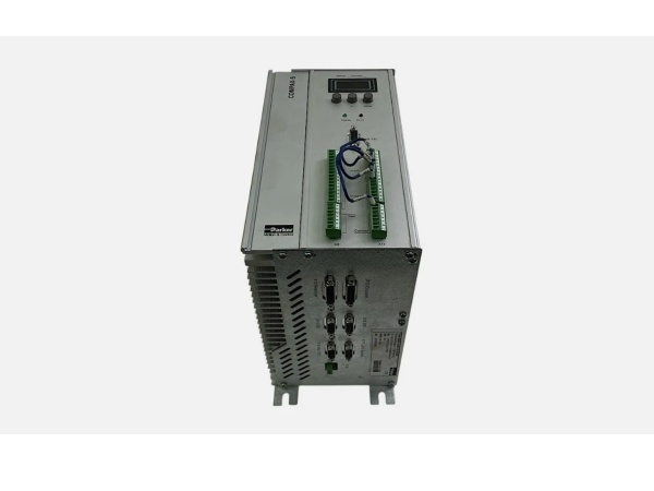
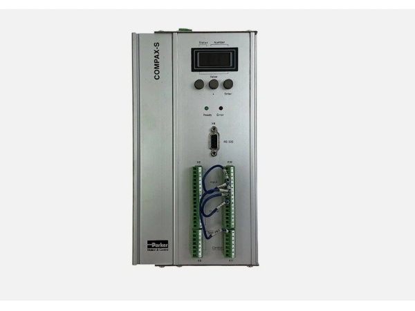
Parker CPX2500S/E3/F3
The Real-World Problem It Solves
The CPX2500S/E3/F3 addresses the challenge of integrating high-performance servo control with flexible I/O capabilities in compact industrial automation systems. Its combination of 2500W power output, vector control precision, and extensive I/O (up to 32 digital I/O, 8 analog I/O) eliminates the need for separate PLC or I/O expansion modules in many applications.
Key advantages over traditional systems:
- Unified Architecture: Combines servo drive, position controller, and I/O module in single unit, reducing cabinet space and wiring complexity
- Multi-Protocol Communication: Supports EtherCAT, CANopen, and DeviceNet simultaneously or alternatively, enabling seamless integration with diverse automation networks
- Vector Control Performance: Delivers high torque at low speeds and precise speed regulation across wide speed range (0-6000 RPM)
- Extended I/O Capability: E3 module variant provides extensive digital and analog I/O for direct sensor/actuator connection without external PLC
Where you’ll typically find it:
- Packaging machinery (filling, labeling, cartoning equipment)
- Printing and converting equipment (register control, web tension)
- Textile manufacturing (winding, cutting, weaving machinery)
- CNC machine tools (feed axes, spindle control)
- Robotics and material handling (pick-and-place, conveyor systems)
- Food and beverage processing (filling, packaging lines)
Bottom line: It delivers industrial-grade servo control with integrated I/O flexibility, multi-protocol networking, and vector control precision in a 2500W package, ideal for applications requiring integrated motion control and field I/O without the complexity of distributed PLC systems.
System Architecture & Operational Logic
The CPX2500S/E3/F3 implements a modular servo control architecture combining high-performance vector control drive with programmable I/O capabilities. The E3 suffix indicates extended I/O module configuration, providing expanded digital and analog interfaces for field device connection.
Control flow and processing logic:
-
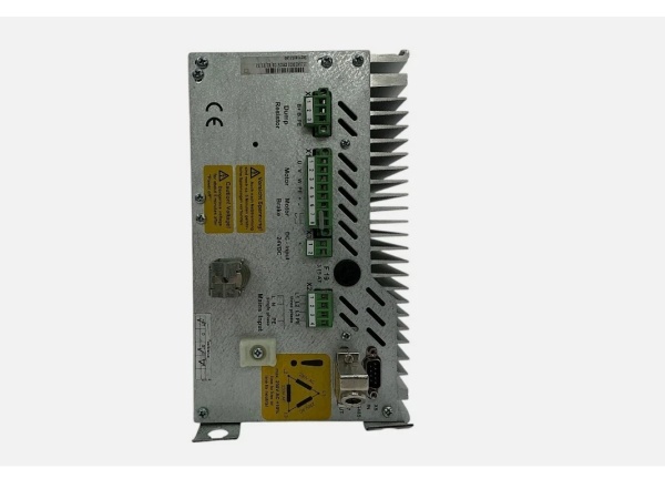
Power Stage Architecture:
- Mains input (200-240 VAC) feeds internal power supply and rectifier
- Control power supply generates 24 VDC for internal electronics and control logic
- DC bus capacitor bank stores energy for motor drive stage
- IGBT inverter stage converts DC bus to 3-phase PWM motor output
- Regenerative braking capability (with external resistor connection)
- Power rating: 2500W continuous output at rated conditions
-
Vector Control Processing:
- Field Oriented Control (FOC) algorithm for high-performance torque control
- Clark/Park transformations convert 3-phase currents to d/q coordinate system
- Current control loops (d-axis for flux, q-axis for torque)
- Velocity control loop with feedforward compensation
- Position control loop with trajectory generation
- Auto-tuning capability for motor parameter identification
-
Feedback System Processing:
- Encoder input processing (Sin/Cos, HTL, incremental, absolute)
- Position feedback interpolation for high resolution
- Velocity estimation from position feedback (derivative calculation)
- Back-EMF sensing for sensorless control (optional mode)
- Encoder emulation output for master/slave configurations
-
I/O Module Processing (E3 Variant) :
- Digital input debouncing and filtering
- Digital output driver with short-circuit protection
- Analog input A/D conversion (12-bit or 16-bit resolution)
- Analog output D/A conversion with calibration
- I/O mapping to drive parameters and control functions
- Programmable I/O functions via software configuration
-
Communication Interface Processing:
- EtherCAT protocol stack for real-time motion control
- CANopen protocol stack for distributed automation
- DeviceNet protocol support (legacy system compatibility)
- RS-232/RS-485 serial communication for parameter access
- Network address management and node identification
- Process data exchange (PDO) and service data exchange (SDO)
-
Protection and Safety Logic:
- Overcurrent detection with immediate shutdown threshold
- Overvoltage monitoring on DC bus
- Overtemperature protection with derating stages
- Short circuit detection on motor outputs
- Ground fault detection and indication
- Fault code generation and storage for diagnostics
-
Motion Profile Generation:
- Trajectory planning (S-curve, trapezoidal profiles)
- Position, velocity, acceleration limiting
- Homing sequence execution (single-turn, multi-turn, encoder index)
- Electronic gearing and camming functionality
- Synchronized motion for multi-axis coordination
Parker CPX2500S/E3/F3
Field Service Pitfalls: Critical Technical Considerations
Mains Voltage Mismatch
Applying incorrect mains voltage (e.g., 480 VAC to 200-240 VAC drive) causes catastrophic power supply failure and potential safety hazards. The drive is designed for specific voltage range and cannot adapt to higher voltages.
- Field Rule: Verify mains voltage at installation site before applying power. Confirm drive model matches supply voltage (200-240 VAC for CPX2500S variant). Check voltage selection if drive supports multiple ranges. Ensure proper grounding and neutral connections. Verify phase sequence if applicable.
Encoder Wiring and Phasing Errors
Incorrect encoder wiring, missing reference signals, or improper phasing causes position feedback errors, servo instability, and potential runaway conditions. The drive must be properly configured for encoder type and resolution.
- Field Rule: Verify encoder wiring matches drive terminal diagram (power, signals, shield). Use oscilloscope to check encoder signals (A, B, index, power supply). Configure encoder parameters (type, line count, resolution) in drive setup. Perform encoder calibration procedure if required. Check encoder power supply voltage (typically 5VDC).
Insufficient Cooling Airflow
The 2500W power output requires adequate forced air cooling to maintain thermal performance. Restricted airflow causes overheating, thermal derating, and potential shutdown during high-current operation.
- Quick Fix: Verify cooling fans are operational and airflow path is unobstructed. Ensure minimum clearance around drive for heat dissipation (10cm recommended). Monitor heatsink temperature during initial operation at full load. Install temperature alarm if required. For cabinet mounting, provide adequate ventilation (minimum 50 CFM per 2.5kW output).
EtherCAT Network Topology Errors
Improper EtherCAT network topology, missing termination, or incorrect master configuration causes communication failures, cyclic frame errors, and unpredictable drive behavior. EtherCAT requires specific network architecture.
- Field Rule: Establish linear EtherCAT topology (no branches unless using switches). Install 100Ω termination resistors at both ends of network segment. Verify network cable quality (Cat5e or higher, shielded). Configure EtherCAT master with correct PDO assignment. Check network redundancy settings if required. Monitor EtherCAT state machine for errors.
Analog I/O Scaling Errors
Incorrect scaling of analog I/O signals causes incorrect sensor readings or actuator control. The analog inputs/outputs must be properly calibrated and scaled to match field device ranges.
- Field Rule: Calibrate analog inputs using known signal sources. Verify 0V/4mA input corresponds to zero reading. Map ±10V input to appropriate engineering units. Verify analog output scaling for actuator control. Use shielded cables for analog signal paths. Test analog I/O accuracy with multimeter before commissioning.
Motor Parameter Identification Failure
Incorrect motor parameters (inductance, resistance, pole pairs) cause poor vector control performance, torque pulsations, and instability. Auto-tuning must be performed with proper load conditions.
- Quick Fix: Ensure proper mechanical coupling before auto-tuning. Perform auto-tuning with no external disturbances. Verify motor nameplate data matches configuration. Record successful tuning parameters for documentation. Manually tune if auto-tuning fails (adjust PI gains, flux reference). Test performance across speed range.
CANopen Network Configuration Errors
Incorrect CANopen baud rate, node ID conflicts, or improper PDO mapping causes communication failures and unpredictable behavior. CANopen requires proper network configuration and node management.
- Field Rule: Verify CANopen baud rate matches network (typically 125 kbps, 250 kbps, 500 kbps, or 1 Mbps). Assign unique node IDs to each device (1-127 range). Configure PDO mapping for required process data. Install 120Ω termination at both ends of network. Use CANopen configuration tool for device setup. Test communication with each node individually.
Regenerative Resistor Selection
Incorrect external braking resistor selection causes resistor overheating, drive overvoltage faults, or potential fire hazard during deceleration of high-inertia loads.
- Field Rule: Calculate required braking energy based on load inertia and deceleration rate. Select resistor with appropriate power rating (continuous and peak). Verify resistance value matches drive specification (typically 10-100Ω range). Mount resistor with adequate heat dissipation and thermal protection. Monitor resistor temperature during initial commissioning. Install resistor with proper fusing if required.
Digital I/O Debouncing and Filtering
Incorrect digital input debouncing settings cause missed signals or false triggering from noisy inputs. Digital output timing issues cause improper actuator control or missed synchronization events.
- Field Rule: Configure input debounce time based on signal characteristics (typically 5-50ms). Verify input filtering settings suppress noise without signal delay. Configure output response times for actuator requirements. Test digital I/O response with actual field devices. Verify I/O mapping matches application requirements. Use appropriate signal voltage levels (5-24 VDC).
Ground Loops and EMC Issues
Improper grounding, missing shield connections, or poor cable routing causes erratic behavior, encoder signal corruption, and intermittent faults. Industrial environments with high EMI require careful installation practices.
- Field Rule: Establish single-point grounding scheme for drive, motor, and field devices. Connect cable shields at drive end only for analog signals. Use shielded cables for encoder and network connections. Maintain minimum 30cm separation from power cables. Install ferrite cores on sensitive signal lines. Verify earth ground continuity (<10Ω). Implement EMC filtering as required.
Software Version Compatibility
Incorrect firmware version or incompatible software tools causes configuration errors, parameter corruption, or limited functionality. The drive requires matching firmware and software versions.
- Quick Fix: Verify current firmware version in drive diagnostics. Check software release notes for compatibility. Update firmware only if required and recommended by manufacturer. Use correct software tool version for drive model. Backup parameters before firmware update. Verify parameter compatibility after update. Document software and firmware versions for maintenance records.
Comparative Analysis: Parker CPX2500S/E3/F3 vs. SC753A-001-01 vs. 6445-001-K-N
| Parameter | Parker CPX2500S/E3/F3 | Pacific SC753A-001-01 | Pacific 6445-001-K-N |
|---|---|---|---|
| Product Type | Servo Drive with I/O | Digital Servo Controller | Stepper Drive/Indexer |
| Motor Type | AC Servo Motors | Brushless Servo Motors | Hybrid Stepper Motors |
| Feedback | Sin/Cos, HTL, 2K-16K encoders | Resolver (12-bit RDC) | Encoder/Optional Resolver |
| Control Type | Vector Control (FOC) | Digital Servo Control | Microstepping with Indexing |
| Power Output | 2500W | 2.2 kW continuous | 300W total |
| Continuous Current | 5A | 7.5 ARMS | 5.0 ARMS |
| Communication | EtherCAT, CANopen, DeviceNet | RS-232/RS-422/RS-485, PacLAN | RS-232/RS-485 |
| Network Support | EtherCAT/CANopen networks | Up to 255 devices (RS-485/PacLAN) | Up to 31 devices (RS-485) |
| I/O Capability | Extended E3 module (up to 32 digital I/O, 8 analog I/O) | Programmable digital/analog I/O | 16 inputs, 12 outputs |
| Programming | Vector control parameters, motion profiles | ServoBASIC Plus (24K memory) | StepperBASIC (12K memory) |
| Speed Range | 0-6000 RPM | Dependent on motor | Dependent on step rate |
| Protection Rating | IP20 (IP54/IP65 optional) | IP65 (optional) | IP65 |
| Key Feature | Unified servo drive + I/O module | Resolver feedback, auto-tuning | Digital Electronic Damping |
| Application Focus | Integrated motion control with field I/O | High-precision servo systems | Precision stepper positioning |
Selection Guidelines:
- Choose Parker CPX2500S/E3/F3 for: Applications requiring integrated servo control and extensive field I/O, EtherCAT/CANopen networking, vector control performance, and unified architecture reducing cabinet components
- Choose Pacific SC753A-001-01 for: Applications requiring resolver feedback for harsh environments, high-power servo control (2.2kW), ServoBASIC programming, and PacLAN multi-axis coordination
- Choose Pacific 6445-001-K-N for: Applications with stepper motors, cost-sensitive precision positioning, indexing applications, and applications requiring Digital Electronic Damping for mid-speed resonance


