
Description
Hard-Numbers: Technical Specifications
Electrical Specifications
-
Power Input:
- Bus Power: 120/240 VAC ±10%, 50/60 Hz, 1-phase or 3-phase (switch selectable)
- Control Logic Power: 90 to 264 VAC, 50/60 Hz
- Line Current: 6 A FLA (Full Load Amperage) at 115V, 6 A FLA at 230V
- Output Power: 2.2 kW continuous (230 VAC, 3-phase), 1.6 kW continuous (230 VAC, 1-phase)
-
Motor Output:
- Continuous Current: 7.5 ARMS
- Peak Current: 15 A (limited to 1 second maximum duration)
- Drive Type: Fully digital IGBT power stage
- Torque Output: 4.8 to 451 lb-in continuous (43.2 to 4038 N·cm)
- Peak Torque: 10 to 800 lb-in (89 to 7150 N·cm)
-
Feedback System:
- Encoder Type: Single resolver feedback
- RDC Resolution: 12-bit (±22 arcmin accuracy)
- Position Resolution: 1024 PPR (Pulses Per Revolution)
- Positioning Accuracy: 0.035°
- Encoder Emulation Modes: Encoder output, Encoder input, Step/Direction input
-
Control Specifications:
- Control Type: Fully digital position, velocity, and torque control
- Programming Language: PacSci ServoBASIC Plus™
- Memory: 24K user memory for program storage
- Automatic Tuning: Digital auto-tuning function enabled
- Update Rate: High-speed digital processing (exact rate not specified in datasheet)
-
Communication Specifications:
- Serial Interfaces: RS-232, RS-422, RS-485
- Network Support: PacLAN port for multi-axis networks
- Maximum Devices: Up to 255 units on single network (RS-485/PacLAN)
- Baud Rate: 9600 baud (standard for Pacific Scientific protocols)
-
I/O Specifications:
- Digital I/O: Programmable digital inputs and outputs
- Analog I/O: Analog input/output capability
- Compatibility: External sensors, actuators, PLC systems, HMI interfaces
- Input Voltage Range: 5-30 VDC compatible (typical for industrial logic)
- Output Sink Current: 50 mA maximum (typical for open-collector outputs)
-
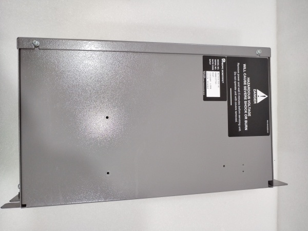
Physical Specifications:
- Dimensions: 9.0″ × 5.5″ × 3.1″ (228 × 140 × 80 mm)
- Weight: 16 lbs (7.3 kg) nominal; 2.5 kg specified by some sources
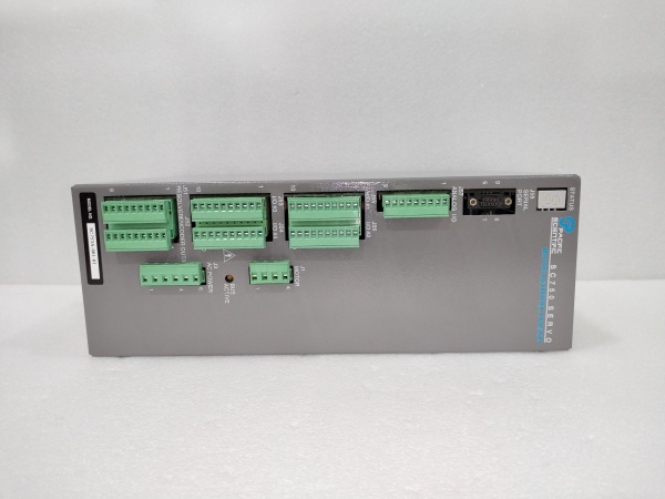
- Mounting: Panel or rack mount, complete front access for connections
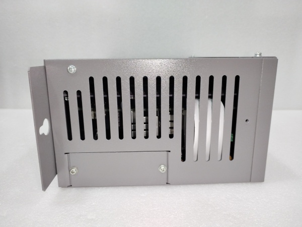
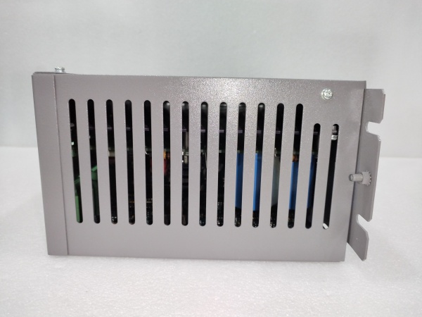
- Cooling: Forced air cooling (internal fans required)
- Enclosure Rating: IP65 (optional, depending on mounting configuration)
-
Environmental Specifications:
- Operating Temperature: 0-50°C at full rated output
- Extended Range: 0-60°C with derating (some sources specify)
- Storage Temperature: -40 to +70°C
- Humidity: 10-90% RH non-condensing
- Altitude: 5000 ft (1500 m) by design
- Protection: Suitable for clean rooms, mild corrosion environments
-
Protection Features:
- Short Circuit Protection: Overcurrent protection on motor outputs
- Overvoltage Protection: Bus voltage monitoring and protection
- Undervoltage Protection: Fault on insufficient supply voltage
- Overtemperature Protection: Thermal monitoring with automatic derating
- Anti-Interference: IGBT power stage design with strong EMI immunity
- Failure Rate: Less than 0.1% (claimed reliability)

Pacific SC753A-001-01
The Real-World Problem It Solves
The SC753A-001-01 addresses the challenge of high-precision servo motor control in demanding industrial environments where reliability, accuracy, and programmability are critical. Its fully digital control architecture eliminates drift issues common in analog systems while providing the flexibility of programmable motion profiles through ServoBASIC Plus.
Key advantages over traditional systems:
- Resolver Feedback Superiority: Unlike optical encoders, resolvers are rugged, temperature-resistant, and immune to contamination from oil, dust, or magnetic fields, making them ideal for harsh industrial environments
- Digital Precision: Combines analog performance characteristics with digital accuracy and repeatability, eliminating component drift and simplifying setup
- Intelligent Motion Control: Built-in auto-tuning reduces commissioning time and ensures optimal servo loop performance across varying load conditions
- Multi-Axis Synchronization: RS-485/PacLAN networking enables coordinated motion of up to 255 axes without additional motion controllers
Where you’ll typically find it:
- CNC machine tools (spindle control, feed axes)
- Medical equipment (surgical robot joints, CT scanner positioning)
- Robotic systems (collaborative robots, AGV navigation)
- Semiconductor manufacturing (wafer handling, lithography equipment)
- Precision assembly lines (pick-and-place, automated inspection)
- Energy equipment (wind turbine pitch control, solar panel tracking)
Bottom line: It delivers industrial-grade servo control with resolver-based ruggedness, programmable flexibility, and multi-axis networking capability in a compact 7.5A/15A power package, ideal for applications requiring precision without compromising reliability.
System Architecture & Operational Logic
The SC753A-001-01 implements a fully digital servo control architecture combining high-speed digital processing with IGBT power amplification and resolver-based position feedback. The controller executes ServoBASIC Plus programs to generate motion profiles while maintaining closed-loop control through resolver feedback.
Control flow and processing logic:
-
Power Stage Architecture:
- AC input (120/240 VAC) feeds internal power conversion stage
- Bus power supply generates DC bus for IGBT inverter stage
- Control logic power supply operates at 90-264 VAC with regulation
- IGBT power stage converts DC bus to 3-phase PWM motor current
- Output power rating: 2.2 kW continuous (3-phase), 1.6 kW (1-phase)
-
Digital Control Processing:
- Fully digital position, velocity, and torque control loops
- Servo loop bandwidth optimized for dynamic response and stability
- Digital auto-tuning algorithm automatically adjusts PID parameters
- Update rate: High-speed digital processing (proprietary specification)
- Zero drift operation: Digital architecture eliminates analog component drift
-
Resolver Feedback System:
- Single resolver input provides position and velocity feedback
- 12-bit Resolver-to-Digital Converter (RDC) with ±22 arcmin accuracy
- 1024 PPR resolution equivalent (12-bit digital conversion)
- RDC processes resolver sine/cosine signals to digital position
- Encoder emulation: Supports encoder output/input/step-direction modes
-
Programming and Memory:
- ServoBASIC Plus interpreter executes user programs
- 24K user memory stores motion programs and parameters
- Complex motion profile generation (position, velocity, torque)
- Conditional branching and loop structures for programmable logic
- Variable storage for data logging and system parameters
-
Communication Interface:
- RS-232 port for single-unit programming and operation
- RS-422/RS-485 for multi-axis networking (up to 255 units)
- PacLAN protocol for coordinated multi-axis motion control
- Address assignment for network identification
- Serial communication at 9600 baud (standard protocol)
-
I/O Processing:
- Digital inputs: External limit switches, start/stop, mode selection
- Digital outputs: Status indicators, alarm outputs, control signals
- Analog I/O: Velocity/position reference signals, monitoring outputs
- Compatibility with PLC and HMI systems via standardized interfaces
-
Protection and Safety Logic:
- Overcurrent protection: Motor output current monitoring and limiting
- Overvoltage protection: DC bus voltage threshold monitoring
- Overtemperature protection: Heatsink temperature sensing with derating
- Short circuit detection: Immediate disable on output fault condition
- Fault output indication: Dedicated fault status signal for external systems
Pacific SC753A-001-01
Field Service Pitfalls: Critical Technical Considerations
AC Input Voltage Mismatch
Applying 240 VAC power with incorrect voltage selection causes catastrophic power supply failure. The controller supports both 120/240 VAC input but requires proper switch configuration or factory setting.
- Field Rule: Verify AC line voltage at installation site before applying power. Confirm controller configuration matches supply voltage (120 VAC for North America/Japan, 240 VAC for Europe/Asia). Check input wiring connections and verify L1, L2, and ground connections match terminal markings. Verify phase sequence for 3-phase applications.
Insufficient Cooling Airflow
The controller requires adequate forced air cooling to maintain rated output. Restricted airflow causes overheating, thermal derating, and potential shutdown during high-current operation. The IGBT power stage generates significant heat at 7.5A continuous output.
- Quick Fix: Verify cooling fans are operational and airflow path is unobstructed. Ensure minimum clearance around controller for heat dissipation. Monitor heatsink temperature during initial operation at full load. Install temperature alarm if required for application. For cabinet mounting, provide forced ventilation with minimum 100 CFM per 2.2kW output.
Resolver Wiring and Phasing Errors
Incorrect resolver wiring or wrong phasing causes position feedback errors, servo instability, and potential runaway conditions. The resolver must be properly phased to the motor to establish correct absolute position reference.
- Field Rule: Verify resolver wiring matches controller terminal diagram (excitation, sine, cosine, common). Use oscilloscope to check resolver signals: sine and cosine should be 90° out of phase. Perform resolver calibration procedure as outlined in programming manual. Verify resolver alignment with motor mechanical reference if required. Check resolver excitation voltage amplitude (typically 7 Vrms).
Auto-Tuning Misconfiguration
Incorrect auto-tuning parameters or inappropriate tuning for load characteristics causes servo oscillation, excessive following error, or sluggish response. Auto-tuning assumes proper load identification and mechanical coupling.
- Quick Fix: Ensure proper mechanical coupling between motor and load before tuning. Perform auto-tuning with no external disturbances. Verify load inertia ratio is within specified range (typically 10:1 load-to-motor inertia). Manually tune PID parameters if auto-tuning results are unstable. Record successful tuning parameters for documentation.
RS-485 Network Address Conflicts
When networking multiple SC753A controllers (up to 255 units), duplicate addresses cause communication failures, unpredictable behavior, and potential data corruption. Address conflicts lead to missed commands and coordination errors.
- Field Rule: Assign unique addresses to each controller in network via dip switches or programming. Document address assignments in system schematics. Verify address range (typically 1-255). Test communication to each node independently before enabling coordinated motion. Use termination resistors at both ends of RS-485 bus for cable lengths over 10 meters.
Peak Current Duration Exceeded
Exceeding the 15A peak current rating beyond 1-second duration causes IGBT overheating and potential permanent damage. The peak rating is for acceleration transients, not continuous operation.
- Field Rule: Verify acceleration profiles do not exceed peak current for more than 1 second. Monitor motor current during operation with controller diagnostic functions. Reduce acceleration rates if peak current duration is excessive. Consider higher-power controller (SC754 series) for applications requiring sustained high current. Implement current limiting in ServoBASIC programs.
Ground Loops and Electrical Noise
Improper grounding, missing shield connections, or cable routing near power conductors causes erratic servo behavior, position errors, and intermittent faults. The resolver feedback system is particularly sensitive to electrical noise.
- Field Rule: Establish single-point grounding scheme for controller, motor, and resolver. Connect resolver cable shield to controller ground at controller end only. Use twisted-pair cables for resolver signals. Maintain minimum 12″ (30 cm) separation from power cables. Install ferrite beads on resolver lines if high-frequency noise is present. Verify earth ground continuity.
Encoder Emulation Mode Selection
Incorrect encoder emulation mode setting causes incompatibility with external motion controllers or PLC systems. The controller must be configured to match the expected input format of the master system.
- Field Rule: Determine required encoder emulation mode for application: encoder output (for following), encoder input (for master), or step/direction (for PLC control). Configure mode via ServoBASIC commands or dip switches. Verify signal levels (5V TTL) and timing characteristics match external system requirements. Test emulation with oscilloscope before full system integration.
Analog I/O Scaling Errors
Improper scaling of analog velocity or position reference signals causes incorrect motor speeds and position errors. The analog input range (typically ±10V) must be properly mapped to velocity/position setpoints.
- Field Rule: Calibrate analog inputs using known voltage sources. Verify 0V input corresponds to zero velocity/position. Map ±10V input to desired velocity range in ServoBASIC code. Verify analog output scaling for position monitoring. Use shielded cables for analog signal paths to minimize noise.
ServoBASIC Program Memory Overflow
Exceeding the 24K user memory limit causes program compilation errors and prevents execution. Complex motion programs with extensive logic can approach memory limits.
- Quick Fix: Optimize ServoBASIC code by eliminating redundant commands. Use subroutines for repeated code sequences. Minimize variable usage and array sizes. Consider modularizing large programs into smaller independent routines. Monitor memory usage during program development. Use external program storage if available for complex applications.
Motor Phase Sequence Errors
Incorrect motor phase wiring causes reverse rotation, reduced torque, and potential motor overheating. The controller must be properly phased to the motor windings to establish correct direction of rotation.
- Field Rule: Verify motor phase connections (U, V, W) match controller output terminals. Test motor rotation direction with low-speed jog command. Swap phase connections if rotation is opposite to required direction. Verify motor phase sequence matches motor nameplate marking. Test all three phases for continuity before power-up.
Safety Circuit Bypass
Using the controller enable input as safety shutdown is prohibited. The enable input only enables the controller; it does not remove power from motor windings or guarantee safe stop.
- Field Rule: Always remove AC power for safety shutdown. Never rely on enable input for personnel protection. Install emergency stop that removes AC power from system. Use safety-rated contactors or disconnects for motor power interruption. Train operators on proper shutdown procedures. Comply with local safety regulations (OSHA, NFPA, IEC).
Comparative Analysis: SC753A-001-01 vs. 6445-001-K-N
表格
| Parameter | SC753A-001-01 (Servo Controller) | 6445-001-K-N (Stepper Drive) |
|---|---|---|
| Motor Type | Brushless servo motor | Hybrid stepper motor |
| Feedback | Resolver (12-bit RDC) | Encoder/StepperBASIC position tracking |
| Control Type | Closed-loop servo control | Open/closed-loop stepper control |
| Continuous Current | 7.5 ARMS | 5.0 ARMS |
| Peak Current | 15 A (1 sec max) | 7.1 A (microstep mode) |
| Resolution | 1024 PPR (±22 arcmin) | 200-51,200 steps/rev |
| Torque Range | 4.8-451 lb-in continuous | Dependent on motor selection |
| Programming | ServoBASIC Plus (24K memory) | StepperBASIC (12K memory) |
| Communication | RS-232/RS-422/RS-485, PacLAN | RS-232/RS-485 |
| Network Support | Up to 255 devices | Up to 31 devices |
| Power Output | 2.2 kW continuous (3-phase) | 300W (internal + external) |
| Key Feature | Resolver feedback, auto-tuning | Digital Electronic Damping |
| Application Focus | High-precision servo systems | Precision positioning, indexing |
Selection Guidelines:
- Choose SC753A-001-01 for: Applications requiring closed-loop servo control, high dynamic performance, resolver feedback for harsh environments, multi-axis coordinated motion (up to 255 axes), and auto-tuning capability
- Choose 6445-001-K-N for: Applications with stepper motors, cost-sensitive precision positioning, indexing applications, simpler motion profiles, and applications requiring Digital Electronic Damping for mid-speed resonance elimination


