
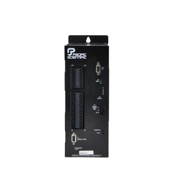
Description
Hard-Numbers: Technical Specifications
Electrical Specifications
-
Input Power:
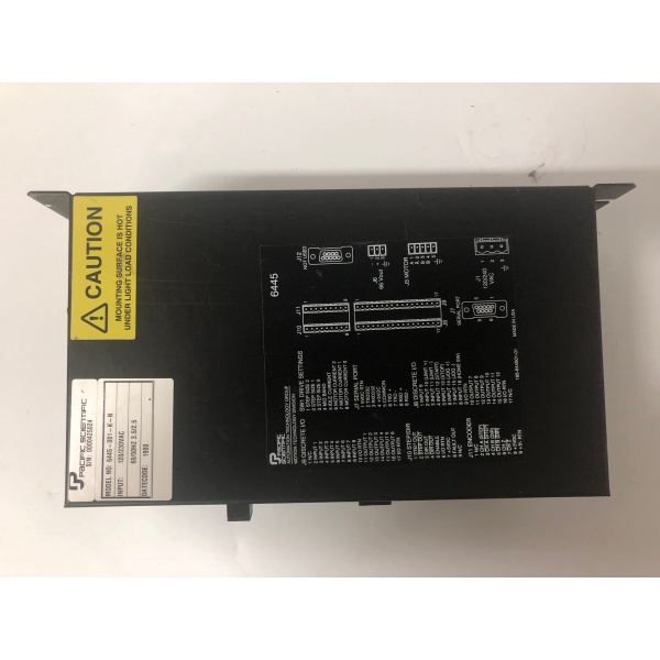
- Voltage: 120/240 VAC ±10%, -15% (switch selectable via SW1)
- Frequency: 50/60 Hz
- Line Current (full load, 300W): 240 VAC – 3.7 ARMS; 120 VAC – 4.7 ARMS
- Internal Supply: PWM switching power supply, 300W ±10% output
-
Motor Output:
- Output Current: 0.625 to 5.0 ARMS (DIP switch selectable in 0.625A increments)
- Peak Current: 7.1 A (microstep mode), 5 A (full step mode)
- Drive Type: Bipolar chopper, 4-phase PWM chopping at 20 kHz frequency
- Phase Configuration: 2-phase (A/B) for 4-lead motors, 4-phase for 8-lead motors
-
External Power Output:
- Voltage: 66 VDC ±3 V
- Current: 4.6 A maximum (combined internal + external)
- Connector: J6 (3-pin pluggable)
- Total Power Capacity: 300W ±10% shared between internal and external drives
-
Control Specifications:
- Step Resolution: 200 to 51,200 steps/revolution (full, half, 1/5, 1/10, 1/25, 1/50, 1/125, 1/250 microstep)
- Base Motor: Standard 1.8° hybrid stepper (200 steps/rev)
- Programming Language: StepperBASIC (100+ instructions)
- Memory: 12K bytes battery-backed RAM
- Communication: RS-232 or RS-422/485, 9600 baud
-
I/O Specifications:
- Inputs: 16 programmable inputs (5-30 VDC compatible)
- Outputs: 12 programmable outputs (50 mA sink max, 16 V off-voltage max)
- Predefined Functions: LIMIT +/-, START/STOP, JOG +/- (6 inputs)
- Motor Moving Indicator: 1 programmable output
- Enable Input: Dedicated input for controller enable
- Fault Output: Open collector (NPN), 100 mA max, 16 V max
-
Encoder Interface:
- Type: Quadrature encoder input
- Functions: Position verification, stall detection, electronic gearing
- Alternative: Step and direction input (configurable)
-
Physical Specifications:
- Dimensions: 6.30″ x 4.25″ x 12.50″ (160 x 108 x 318 mm)
- Weight: 10 lbs (4.54 kg) nominal
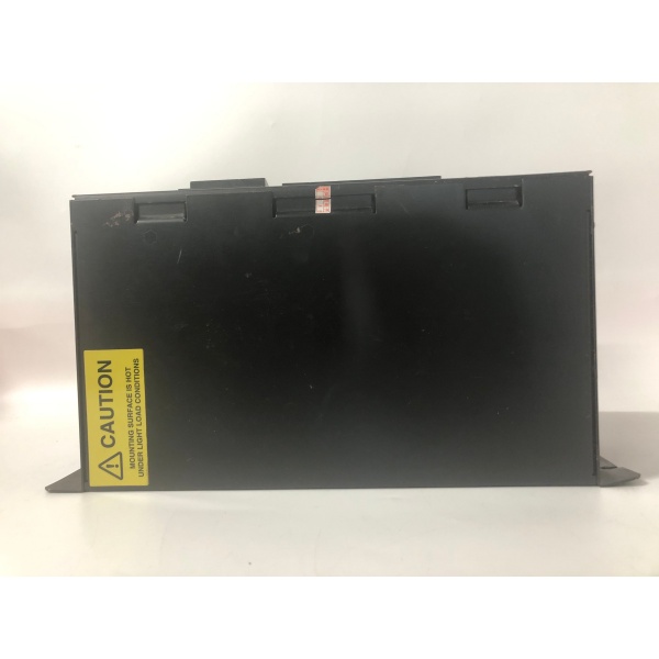
- Mounting: Standard 8″ (205 mm) deep NEMA enclosure, #10 (M5) bolts
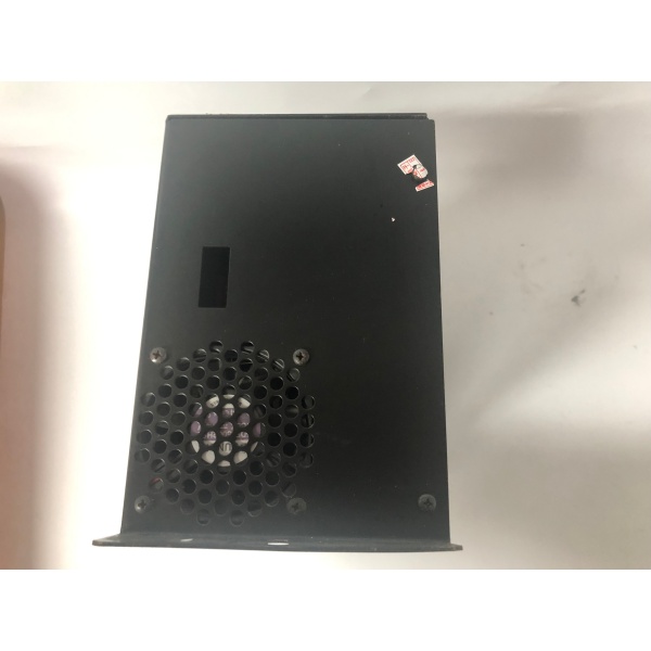
- Cooling: Internal fan, requires 4″ (10 cm) clearance at bottom and top
-
Environmental Specifications:
- Operating Temperature: 0-50°C ambient (at full rated current)
- Storage Temperature: -40 to +70°C
- Humidity: 10-90% RH non-condensing
- Altitude: 5000 ft (1500 m) by design
- Vibration: IEC Standard 68-2-6 compliant
-
Protection Features:
- Short Circuit Protection: Disables drive on motor output short circuit (power cycle to clear)
- Overvoltage Protection: Shunt regulator disables drive if DC bus exceeds 84V
- Undervoltage Protection: Fault if 66V external supply drops below 55V
- Digital Electronic Damping: Patented circuit to eliminate mid-speed instability
- Idle Current Reduction: Reduces motor current by 50% after 0.1 second idle period

6445-001-K-N
The Real-World Problem It Solves
The 6445-001-K-N addresses the challenge of precise stepper motor control with high torque output across a wide speed range. Its patented Digital Electronic Damping eliminates torque loss and stalling conditions common in stepper systems at mid-range speeds (typically 200-1000 RPM). The integrated StepperBASIC indexer provides programmable motion control without requiring external controllers, simplifying system integration and reducing component count.
Where you’ll typically find it:
- X-Y positioning tables and slides in CNC equipment
- Packaging machinery with precise indexing requirements
- Feed-to-length cutting systems
- Labeling and printing machines
- Semiconductor wafer handling equipment
- Automated assembly systems
Bottom line: It delivers high-resolution microstepping with patented damping technology, programmable control via StepperBASIC, and flexible I/O integration for applications requiring precise stepper motor positioning without the cost of servo systems.
System Architecture & Operational Logic
The 6445-001-K-N implements a dual-architecture system combining a high-performance bipolar chopper drive with a programmable indexer. The drive stage uses PWM chopping at 20 kHz to regulate motor currents precisely, while the indexer executes StepperBASIC programs to generate motion profiles and manage I/O.
Control flow and processing logic:
-
Power Stage:
- AC input (120/240 VAC selectable via SW1) feeds internal PWM switching supply
- Main supply generates 66VDC bus for motor drive and external drive output
- Shunt regulator monitors DC bus voltage and disables drive if exceeds 84V
- 66VDC output at J6 provides power to additional drive (total 300W shared)
-
Drive Stage:
- Bipolar chopper topology with 4-phase PWM chopping at 20 kHz
- Current regulation via DIP switches (S1) selecting 0.625 to 5.0 ARMS
- Microstep resolution via DIP switches: full, half, 1/5, 1/10, 1/25, 1/50, 1/125, 1/250
- Digital Electronic Damping circuit advances or delays switching relative to pulse train to damp mid-speed oscillations
-
Indexer Stage:
- StepperBASIC interpreter executes user programs (100+ instructions)
- Program storage in 12K battery-backed RAM
- Motion profile generation: position, velocity, acceleration profiles
- I/O management: 16 inputs, 12 outputs, encoder interface processing
-
Communication Interface:
- RS-232 for single-unit control (programming and operation)
- RS-422/485 for multi-unit control (up to 31 units per network)
- Address selection via DIP switches (S2) for multi-drop configurations
- 9600 baud serial communication
-
I/O Processing:
- Inputs (J8, J9): 5-30 VDC compatible, programmable function assignment
- Outputs (J8, J9, J10): Open collector, 100 mA max, programmable under software
- Encoder (J11): Quadrature signals for position verification and electronic gearing
- Step/Dir Out (J10): Provides step and direction signals for external drive following
-
Protection Logic:
- Short circuit detection on motor outputs
- Overvoltage monitoring (84V shunt regulator trip point)
- Undervoltage monitoring (55V fault threshold for external supply)
- Fault output activation (NPN open collector) on any fault condition
6445-001-K-N
Field Service Pitfalls: Critical Technical Considerations
AC Switch Setting Error
Applying 240 VAC with AC switch (SW1) in 120 VAC position permanently damages the drive. This is a critical installation error that destroys the power supply.
- Field Rule: Always verify AC line voltage at installation site before setting SW1. Remove power, open cover, confirm switch position matches supply voltage (120 VAC for USA/Japan, 240 VAC for Europe/Asia). Reinstall cover before applying power.
Motor Current Selection Exceeds Rating
Setting drive current higher than motor winding current rating (5.0 ARMS max) causes motor overheating and potential winding failure. Motor case temperature must not exceed 100°C.
- Quick Fix: Verify motor winding current rating from motor nameplate. Set DIP switches (S1) to drive current equal to or less than motor rating. Monitor motor temperature during initial operation. Use thermal imager or contact thermometer if available.
Missing Ground Connections
Operating without motor case grounded to earth ground and drive chassis grounded creates shock hazard and can cause erratic behavior due to ground loops.
- Field Rule: Connect motor case ground (J3 pin 5) to earth ground. Connect drive chassis ground (J1 pin 3) to earth ground. Use separate earth ground stud on front of 6445. Verify continuity between ground points before power-up.
66V External Supply Voltage Drop
When powering additional drive from J6 66V output, cable length over 3 feet (0.9 m) without capacitor causes voltage drop below 55V, triggering undervoltage fault on both drives.
- Field Rule: For cable lengths over 3 feet, install aluminum electrolytic capacitor (maximum 1000 µF, 100 VDC, 2A ripple current minimum) at additional drive input. Use twisted pair plus grounding cable (16, 18, or 20 AWG). Calculate total load current and ensure it remains below 4.6A.
Mid-Speed Range Stalling
Stepper motors lose torque and stall at mid-range speeds (typically 200-1000 RPM) due to resonance. Without Digital Electronic Damping enabled, applications experience lost motion and position errors.
- Quick Fix: Enable Digital Electronic Damping via DIP switch or software command. This patented circuit damps oscillations by advancing or delaying current switching relative to pulse train. Verify operation through mid-speed range during commissioning.
Encoder Wiring Errors
Incorrect encoder wiring or missing termination causes erratic position verification, stall detection failures, and electronic gearing errors. Quadrature encoder requires proper phase relationship.
- Field Rule: Use line driver encoder with proper termination. Verify phase A, phase B, index Z, +5V, and ground connections. Check encoder specification for termination requirements (typically 120Ω). Configure input for quadrature mode (factory default) before use.
Serial Address Conflicts in Multi-Drop Systems
When using RS-422/485 multi-drop configuration (up to 31 units), duplicate addresses cause communication failures and unpredictable drive behavior.
- Field Rule: Set unique addresses via DIP switches (S2) for each drive in network. Address range typically 0-30. Verify addresses are unique before powering up system. Document address assignments in system documentation.
Insufficient Cabinet Cooling
The 6445 dissipates 50W at 5A full load current (20W at 2.5A). Cabinets without adequate cooling cause internal temperature to exceed 50°C, leading to drive derating or shutdown.
- Field Rule: Calculate cabinet heat load based on drive count and current settings. Provide filtered ventilation with minimum 100 CFM airflow per 50W dissipation. Monitor internal cabinet temperature during initial operation. Install temperature alarm if required.
Enable Input Misuse
Using enable input as safety shutdown is prohibited. Enable input only enables controller; it does not remove power from motor windings. For safety shutdown, remove AC power from J1.
- Field Rule: Always remove AC power for safety shutdown. Never rely on enable input for personnel protection. Install emergency stop that removes AC power from system. Train operators on proper shutdown procedures.
Step and Direction Output Loading
Step and direction output at J10 cannot drive long cable runs or multiple inputs without buffering. Exceeding fan-out capability causes signal degradation and missed steps.
- Field Rule: Use Step/Dir output to drive single external device or buffer. Verify external input impedance matches output specifications. For multiple drives, use RS-422/485 multi-drop configuration instead of cascading Step/Dir outputs.
Cable Shielding and Twisting
Non-shielded or untwisted motor and signal cables pick up electrical noise from nearby power conductors, causing erratic motion, missed steps, and position errors.
- Field Rule: Use shielded, twisted-pair cables for motor connections (J3). Use shielded cables for encoder (J11), serial (J7), and I/O (J8, J9, J10). Connect shields to ground at drive end only for signal cables (single-point grounding). Maintain 12″ (30 cm) separation from power conductors where possible.


