
Description
Hard-Numbers: Technical Specifications
-
System Capacity:
- Maximum stall torque: 137 Nm (200 V) / 114 Nm (100 V)
- Maximum output torque: 147 Nm
- Maximum starting torque: 5.4 Nm
- Rotor moment of inertia: 0.075 kg·m²
- Maximum velocity: 3 s⁻¹ (rps)
- Position sensor resolution (resolver): 614,400 ppr (12-bit) or 409,600 ppr (10-bit)
- Position feedback output (øA/øB): 12-bit: 153,600 ppr / 10-bit: 102,400 ppr; øZ: 12-bit: 38,400 ppr / 10-bit: 25,600 ppr
- Allowable axial load: 9,500 N
- Allowable moment load: 156 N·m
- Mass (motor): 40 kg; Driver: 2.9 kg (standard) / 3.0 kg (absolute version)
-
Power Requirements:
- Driver main power (ESA-1010A35): 200–220 VAC ±10%, 50/60 Hz, single-phase
- Driver main current (max, excluding inrush): 7.5 A (200 VAC)
- Main capacity: 2.5 kVA
- Inrush current: 140 A
- Control power: 100–110 VAC or 200–220 VAC; 50 VA (excluding inrush)
- Leakage current: 40 Hz–1 kHz: 5 mA rms; 1 kHz–1 MHz: 35 mA rms
- Regenerative braking: Internal dump resistor; optional external resistor for high-inertia, high-duty cycles
-
Environmental Ratings:
- Driver operating ambient: 0–50°C (free from condensation, dust, corrosive gas)
- Driver storage: 20–70°C
- Motor operating ambient: 0–40°C; humidity: 20–80% (no condensation, dust, corrosive gas)
- Vibration resistance: 0.5 G (JIS-C0911)
- Line noise immunity: 1,500 V, 1 µs (noise simulator)
-
Control & Interface:
- Control modes: Torque (SL=1), Velocity (SL=2), Position (SL=3)
- Position feedback output: Line driver (øA/øB/øZ); øZ line driver or open-collector selectable via JP1
- Position feedback resolution: 10-bit or 12-bit (parameter FR)
- Command sources: Pulse train (CW/CCW, Step+Direction, Quadrature), RS-232C serial, Programmable Indexer (64 channels), Analog velocity (±10 V), Analog torque (±10 V)
- Monitoring: Analog velocity monitor pins, RS-232C monitor (position, alarm, parameters)
- Communication: Asynchronous RS-232C, 9,600 bps
- Data backup: EEPROM (500,000 write/erase cycles)
-
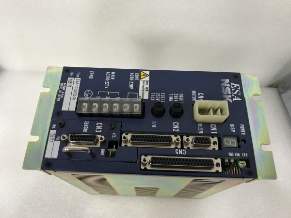
Connector & Wiring:
- CN1: RS-232C (DE-9), supports Handy Terminal FHT11
- CN2: 25-pin control I/O (signals: Servo On, Emergency Stop, Pulse Train, In-Position, Home, Alarm, Brake, etc.)
- CN5: 37-pin extended I/O (signals: Near A/B, Velocity Report, Target Proximity, Over-Travel, etc.)
- CN3: Resolver cable (15-pin)
- CN4: Motor power cable (connects to exclusive motor cable)
- Power terminal block: MAIN AC200–220V, CONT. AC100–220V (control), FGND
- Grounding: FG terminal; single-point grounding; driver and motor separately grounded
- Wiring precautions: Use shielded, twisted-pair for I/O and resolver/pulse; length ≤2 m; separate from power lines; shield to frame ground at one end
-
Safety & Protection:
- Fuses: FUSE1, FUSE2: 250 V, T10A
- Emergency Stop: Must connect to EMST (CN2) for immediate motor stop
- Over-Travel: Hardware (input) and software limits
- Regeneration: High-inertia/high-duty cycles may require external dump resistor
- Discharge wait: After power off, wait ≥5 minutes before removing cover (capacitors)
- IP protection: Driver must be in IP54 or better enclosure; protect from oil, mist, chips, paint fumes
-
Functional Capabilities:
- Programmable Indexer: 64 channels
- Home Return sequence: Built-in; configurable parameters (HA, HD, HV, HO, HW, HZ, HS, HI)
- Auto-tuning: Available (Level 1/2)
- Digital filters: Low-pass FP/FS; Notch NP/NS; Feed-forward FF; Integration limiter ILV; Dead-band DBP
- Gain switching: Automatic gain switching based on velocity or timer
- Soft-start/acceleration profiling: Configurable acceleration/deceleration
- Brake control: For motors with electromagnetic brake (C/D/G suffixes)

NSK ESA-1010A35-21.1
The Real-World Problem It Solves
When you need high-torque, zero-backlash rotary positioning with sub-arcsecond repeatability, the ESA-1010A35 paired with RS1010FN001 eliminates mechanical transmission components (gearboxes, couplings) and reduces lost motion. Its resolver-based feedback provides high resolution and robustness in electrically noisy environments, while the driver supports multiple command interfaces and auto-tuning, simplifying integration with PLCs, motion controllers, and PC-based systems.
Where you’ll typically find it:
- Precision rotary tables and indexers in semiconductor and electronics manufacturing
- Robot joints (wafer handling, assembly, inspection) requiring direct-drive torque
- Machine tools (rotary axes, C-axis, B-axis) with high stiffness and positioning accuracy
- Coordinate measuring machines (CMM) rotary axes
- Test equipment and aerospace assembly requiring precise angular control
Bottom line: It delivers high torque density and precision in a direct-drive architecture, with resolver feedback for reliability, and a driver that accommodates various command sources and tuning methods for rapid deployment.
System Architecture & Operational Logic
The ESA-1010A35 driver unit implements a full closed-loop P/PI positioning control with a resolver-based position sensor. The driver converts command sources (pulse train, RS-232C, analog velocity/torque, or internal indexer) into torque commands via velocity and position loops. The resolver feedback provides high-resolution position and velocity signals; optional absolute position sensors (C-suffix drivers/motors) enable absolute positioning without mechanical homing (with certain limitations).
Signal flow and processing logic:
-
Power Stage:
- AC main input (200–220 VAC) powers internal switching amplifiers and control circuitry.
- Control power (100–110 VAC or 200–220 VAC) feeds logic and interfaces.
- Internal dump resistor dissipates regenerative energy; external resistor may be added.
- Fuses protect against overcurrent; capacitors hold charge after power-off.
-
Resolver Interface (CN3) :
- Resolver cable carries excitation and feedback signals between motor and driver RDC.
- Resolver-to-digital converter (RDC) provides high-resolution position (12-bit/10-bit via RR).
- Resolver error alarms detect open/short/faults.
-
Command Interfaces:
- CN2 and CN5 accept pulse train, digital I/O (Servo On, Emergency Stop, Home, Brake, In-Position, Alarm, Over-Travel).
- CN1 RS-232C accepts serial commands from PC or Handy Terminal; supports parameter read/write, monitoring, and program upload.
- Analog input (±10 V) for velocity or torque commands.
- Internal Programmable Indexer executes stored motion programs (64 channels).
-
Control Loops:
- Position loop (P or PI) processes position error (command minus feedback).
- Velocity loop (P or PI) processes velocity error, using VG (velocity gain) and VI (velocity integrator frequency).
- Current/torque stage converts commanded torque to motor phase currents.
- Filters (FP/FS, NP/NS), feed-forward (FF), dead-band (DBP), and integration limiter (ILV) shape performance.
-
Feedback & Monitoring:
- Line driver outputs (øA/øB/øZ) provide quadrature position feedback for external controllers.
- Analog velocity monitor pins output velocity-proportional voltage.
- RS-232C monitor outputs position, alarm status, parameter values, and program execution history.
-
Safety & Protection:
- Emergency Stop (EMST) immediately stops motor.
- Over-Travel (software and hardware) prevents motion beyond limits.
- Alarms include overcurrent, overheat, resolver error, position error, CPU error, main/control AC line faults, etc.
- Regeneration management prevents overvoltage during deceleration.
-
Optional Absolute Positioning:
- For ESAC5 drivers and motors with absolute position sensor (C-suffix), absolute positioning is available.
- Requires matching serial numbers between driver and motor; PA data must correspond.
- Home repeatability can degrade if serial numbers mismatch.
NSK ESA-1010A35-21.1
Field Service Pitfalls: What Rookies Get Wrong
Mismatched Serial Numbers Between Driver and Motor
The ESA driver stores motor-specific PA (compensation) data; swapping drivers or motors with non-matching serial numbers reduces precision and degrades home repeatability (especially with absolute sensors).
- Field Rule: Always verify the driver serial number plate and motor serial number plate match before commissioning. If replacing either, perform re-initialization or obtain a matched set from NSK.
Extending or Shortening the Cable Set
Cutting the cable set to shorten it or extending it with non-specified cable changes impedance and capacitance, leading to resolver errors and noisy feedback.
- Quick Fix: Use only the specified cable set (M-CXXXSSR05) with correct length. If different length is required, order the proper NSK cable (M-CXXXSSR05 with XXX in meters). Maximum standard length is 30 m; consult NSK for longer runs.
Incorrect Grounding or Missing FG Connection
Improper grounding causes noise in resolver and pulse signals, resulting in erratic motion, alarms, or reduced accuracy.
- Field Rule: Connect driver FG terminal to building/frame ground using proper gauge wire. Ground motor separately to its frame. Use single-point grounding; avoid loops. Use shielded cables for CN2/CN5/resolver; connect shield to frame ground at one end (typically driver side).
Insufficient Clearance Around Driver for Heat Dissipation
Installing the driver in an enclosure without at least 100 mm clearance above/below or without ventilation can cause overheating and premature failure.
- Field Rule: Maintain ≥100 mm clearance above and below the driver. Provide ventilation openings on top if heat builds up. Install in IP54 or better enclosure; protect against oil, mist, chips, and paint fumes. For high-duty cycles, consider forced air cooling or external enclosure.
Overlooking Inrush Current When Sizing Power Supply
The driver’s inrush current (140 A) can trip breakers if not accounted for, especially with multiple drives on one circuit.
- Field Rule: Use delay-type breakers or size power supply to accommodate inrush. For multiple drives, consider staggered power-on or consult NSK for distribution recommendations.
Failing to Wait for Capacitor Discharge Before Opening Cover
Capacitors retain high voltage for several minutes after power-off; opening the cover too early poses shock risk and can damage components.
- Field Rule: After turning off main and control power, wait at least 5 minutes before removing the driver cover. If only main power was turned on, turn on control power for 5+ seconds, then turn both off and wait 5 minutes.
Ignoring Regeneration in High-Inertia Applications
Heavy inertial loads decelerating rapidly generate high regeneration; internal resistor may overheat, causing “Abnormal main power voltage” alarm.
- Field Rule: Calculate regeneration energy; if duty cycle and inertia are high, reduce deceleration rate or velocity, or install an external high-capacity dump resistor. Monitor driver temperature and regeneration resistor heat.
Incorrect Resolver or Pulse Cable Wiring
Wrong pin assignments or using unshielded cable causes resolver errors, noise, and loss of position.
- Field Rule: Use exclusive NSK resolver and motor cables; follow pin-out in the manual. For pulse train and feedback, use twisted-pair shielded cables; keep length ≤2 m. Separate signal cables from power lines; shield to frame ground at one end.
Omitting Emergency Stop Connection
Not connecting EMST to CN2 removes a critical safety path, which may violate local safety standards and prevent immediate motor stop in emergencies.
- Field Rule: Always connect Emergency Stop signal to EMST on CN2. Configure system to stop motor immediately upon E-Stop activation, even when using RS-232C or internal indexer.


